29
Auxiliary Equipment
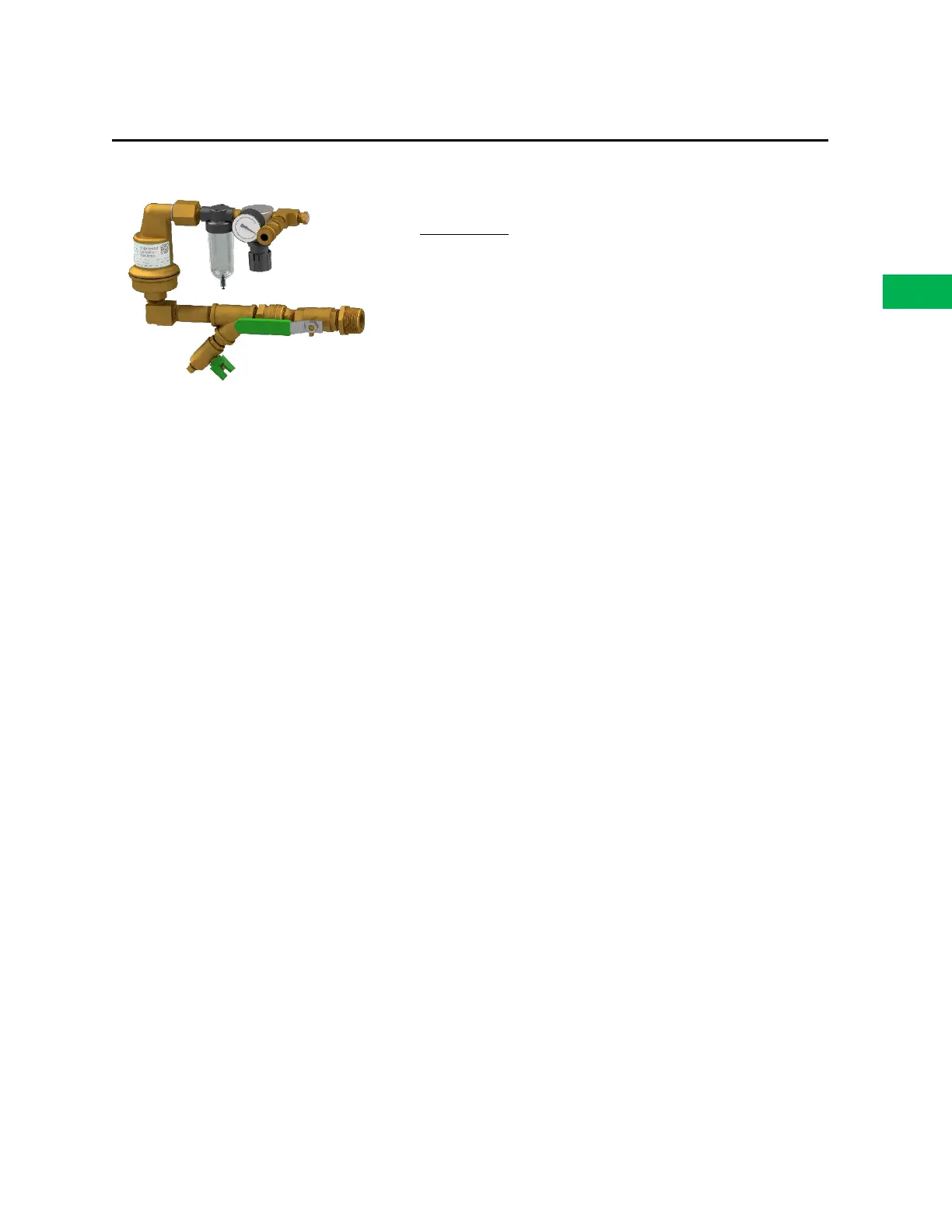
OXYGEN REMOVAL VENT: STANDARD VENT PAV-D/DQ
Specifications
Stock Number: PAV-D/DQ
Service Pressure: Up to 175 PSIG (12 Bar)
System Connection: 1” NPT Male
Temperature Range: 40°F to 120°F (4.5°C to 49°C)
Dimensions: 13.5” (W) X 7.5” (H) X 4.25” (D)
(343mm (W) X 191mm (H) X 108mm (D))
Support Hanger Not Required
General Description
The ECS Standard Vent (PAV-D/DQ) provides oxygen venting in dry pipe and preaction fire sprinkler
systems. As a fire sprinkler system is filled with a continuous supply of nitrogen gas from the nitrogen
generator system, the PAV-D/DQ allows oxygen rich gas to be vented from the fire sprinkler system. Over
a short period of time the vent will almost completely remove oxygen from the fire sprinkler system (less
than 2% oxygen). The vent is equipped with a levered float valve that prevents water from passing through
the restricted venting orifice when water enters the fire sprinkler system. The in-line filter protects the
restricted venting orifice from contaminants from the sprinkler system. A backpressure regulator is
included to prevent total system depressurization from the vent assembly during the venting process. The
restricted venting orifice allows oxygen to be vented from the fire sprinkler system at a controlled rate to
achieve a minimum of 98% nitrogen concentration. A special push fitting is provided to receive 5/32”
tubing when the vent is used in conjunction with the SMART Gas Analyzer or the AdvancedIQ Vent
Controller.
Installation Instructions
1. The vent is equipped with a ball valve to be connected to the fire sprinkler riser. The contractor
must install a 1” outlet (welded or mechanical) to connect the vent assembly to the sprinkler
system on the system side of the main control valve. The ball valve must remain in the closed
position until the nitrogen generator system has been commissioned.
NOTE: The vent assembly does not require a support hanger.
2. Install the vent assembly in a level position. Recommended mounting height is 5’-10’ (2-3m) above
the finished floor, but a minimum of 2’ (.6m) above the dry pipe or preaction control valve.
NOTE: Piping to the vent assembly cannot be installed in a configuration that would trap water
and prevent drainage to the sprinkler system; a water trap impedes the ability of the vent
assembly to vent oxygen from the fire sprinkler system.
3. Inspection of the vent assembly should be performed after installation and hydrostatic testing of
the fire sprinkler system. Inspection should be performed periodically thereafter in accordance
with the applicable national codes, NFPA codes and standards, and/or the authority having
jurisdiction.