22
Installing the Motherboard
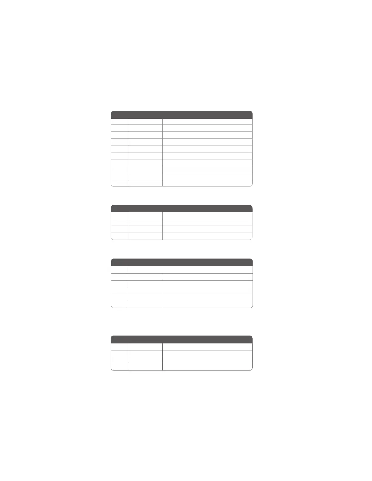
Pin Signal Name
F_AUDIO1: Front Panel Audio header
This header allows the user to install auxiliary front-oriented microphone and line-out ports
for easier access.
CD_IN: Analog audio input connector
1 AUD_MIC Front Panel Microphone input signal
2 AUD_GND Ground used by Analog Audio Circuits
3 AUD_MIC_BIAS Microphone Power
4 AUD_VCC Filtered +5V used by Analog Audio Circuits
5 AUD_F_R Right Channel audio signal to Front Panel
6 AUD_RET_R Right Channel Audio signal to Return from Front Panel
7 REVD Reserved
8 Key No Pin
9 AUD_F_L Left Channel Audio signal to Front Panel
10 AUD_RET_L Left Channel Audio signal to Return from Front Panel
Pin Signal Name Function
1 CD in_L CD In left channel
2 GND Ground
3 GND Ground
4 CD in_R CD In right channel
Pin Signal Name Function
IR1: Infrared header
Not assigned
2 Key
No pin
Pin Signal Name Function
3 +5V
IR Power
4 GND Ground
1 Not Assigned
5 IR_TX IrDA serial output
6 IR_RX IrDA serial input
SPDIFO1: SPDIF out header
This is an optional header that provides an S/PDIF (Sony/Philips Digital Interface) output
to digital multimedia device through optical fiber or coaxial connector.
Pin Signal Name Function
Pin Signal Name Function
1 SPDIF SPDIF digital output
2 +5VA 5V analog Power
3 Key No pin
4 GND Ground
 Loading...