EasyManua.ls Logo

ECS H310CH5-TI2

ECS H310CH5-TI2
22 pages
To Next Page IconTo Next Page
Loading...
H310CH5-TI2 USER MANUAL
The information in this document is subject to change without notice. The
manufacturer makes no representations or warranties with respect to the contents
hereof and specifically disclaims any implied warranties of merchantability or
fitness for any particular purpose. The manufacturer reserves the right to revise this
publication and to make changes from time to time in the content hereof without
obligation of the manufacturer to notify any person of such revision or changes.
This equipment has been tested and found to comply with the limits for a Class B
digital device, pursuant to Part 15 of the FCC Rules. These limits are designed to
provide reasonable protection against harmful interference in a residential
installation. This equipment generates, uses, and can radiate radio frequency
energy and, if not installed and used in accordance with the instructions, may cause
harmful interference to radio communications. However, there is no guarantee that
interference will not occur in a particular installation. If this equipment does cause
harmful interference to radio or television reception, which can be determined by
turning the equipment off and on, the user is encouraged to try to correct the
interference by one or more of the following measures:
Reorient or relocate the receiving antenna
Increase the separation between the equipment and the receiver
Connect the equipment onto an outlet on a circuit different from that to
which the receiver is connected
Consult the dealer or an experienced radio/TV technician for help
Shielded interconnect cables and a shielded AC power cable must be employed with
this equipment to ensure compliance with the pertinent RF emission limits
governing this device. Changes or modifications not expressly approved by the
system’s manufacturer could void the user’s authority to operate the equipment.
Federal Communications Commission (FCC)
Disclaimer
Declaration of Conformity
This device complies with part 15 of the FCC rules. Operation is subject to the follow-
ing conditions:
This device may not cause harmful interference.
This device must accept any interference received, including interference
that may cause undesired operation.
Electromagnetic compatibility of multimedia equipment - Emission
requirements
EN 55032
EN 61000-3-2
Electromagnetic Compatibility(EMC)
Part 3-2: Limits-Limits for harmonic current emissions (equipment input
current 16A per phase)
EN 61000-3-3
Electromagnetic Compatibility(EMC)
Part 3-3: Limits-Limitation of voltage changes, voltage fluctuations and flicker
in public low-voltage supply systems, for equipment with rated current 16A
per phase and not subject to conditional connection
EN 55024
Information technology equipment-Immunity characteristics-Limits and
methods of measurement
EN 60950
Safety for information technology equipment including electrical business
equipment
CE marking
This device is in conformity with the following EC/EMC directives:
Question and Answer IconNeed help?

Do you have a question about the ECS H310CH5-TI2 and is the answer not in the manual?

ECS H310CH5-TI2 Specifications

General IconGeneral
Form FactorMicro ATX
ChipsetIntel H310
CPU SocketLGA 1151
Memory TypeDDR4
Memory Slots2
Max Memory32 GB
Storage4 x SATA 6Gb/s
CPU Support8th/9th Gen Intel Core/Pentium/Celeron
Expansion Slots1 x PCIe x16, 2 x PCIe x1
USB Ports2 x USB 2.0
Video Outputs1 x HDMI
LANRealtek RTL8111H Gigabit LAN
AudioRealtek ALC887

Summary

Disclaimer

Federal Communications Commission (FCC)

Declaration of Conformity

Brief Introduction

Specifications

CPU Specifications

Details CPU socket type and maximum wattage supported.

Chipset Details

Identifies the onboard Intel H310 Chipset.

Memory Support

Specifies dual channel memory architecture and DDR4 support.

Expansion Slots

Lists M.2 slots for WiFi/BT and SSDs.

Storage Interface

Outlines support for SATA storage devices.

Audio Codec

Describes the 6-channel HD audio codec.

LAN Controller

Details the Gigabit LAN controller and wake-up features.

Rear Panel IO Ports

Lists all external connectors on the motherboard's rear panel.

Internal IO Connectors and Headers

Details internal headers for fans, USB, and front panel connections.

System BIOS Features

Lists BIOS features, recovery, display, and boot options.

Motherboard Form Factor

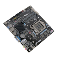
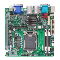
Specifies the motherboard's physical dimensions as Thin Mini ITX.

Motherboard Components Identification

CPU Socket

LGA1151 socket for Intel® Coffee Lake Processor.

M.2 Socket (Key-M)

M.2 socket (Key-M) for SSDs (SATA/PCIe Gen.2).

Clear CMOS Jumper

Clear CMOS jumper for resetting BIOS settings.

M.2 Socket (Key-E)

M.2 socket (Key-E) for WiFi (PCIe Gen.2) / BT.

Speaker Header

2 Channels audio speaker header for All-In-One specification.

Digital Microphone Header

Digital microphone header for All-In-One specification.

Front Panel Audio Header

Front panel audio header for audio connections.

Bluetooth Module

Onboard Bluetooth functionality.

Case Open Header

Case open header for security monitoring.

DDR4 SO-DIMM Sockets

DDR4 SO-DIMM sockets for memory modules.

SATA Power Connector

SATA power connector for storage devices.

USB 2.0 Header (Card ReaderCamera)

USB 2.0 header (black) for card reader/camera.

USB 2.0 Header (Touch Panel)

USB 2.0 header (yellow) for touch panel.

Front Panel USB 3.0 Header

Front panel USB 3.0 header for high-speed devices.

SATA 6 Gbs Connectors

Serial ATA 6Gb/s connectors for storage devices.

System Fan Connector

4-pin system cooling fan connector with smart fan function.

CPU Fan Connector

4-pin CPU cooling fan connector with smart fan function.

Onboard Serial Port Header

Onboard serial port header for legacy devices.

Front Panel Header

Front panel switch/LED header for case controls.

Consumer Infrared Header

Consumer infrared header for remote control.

LVDS Connector

LVDS connector for specific display connections.

LVDS Brightness Switch Header

LVDS brightness switch header for display adjustment.

LVDS Brightness Control Header

LVDS brightness control header for display adjustment.

LCD Panel Select Jumper

LCD panel select jumper for display configuration.

Trusted Platform Module Header

Trusted platform module header for security.

Header Pin Definition and Jumper Settings

Front Panel Header Pinout

Pin definition for front panel switches and LEDs.

Front Panel Audio Header Pinout

Pin definition for front panel audio connections.

COM Port Header Pinout

Pin definition for the onboard serial port header.

USB 2.0 Header (Card ReaderCamera) Pinout

Pin definition for USB 2.0 header for card reader/camera.

Speaker Header Pinout

Pin definition for the speaker header.

Fan Connectors Pinout

Pin definition for system and CPU fan connectors.

Chassis Intrusion Detection Pinout

Pin definition for chassis intrusion detection.

Consumer Infrared Header Pinout

Pin definition for the consumer infrared header.

Digital Microphone Header Pinout

Pin definition for the digital microphone header.

Trusted Platform Module Header Pinout

Pin definition for the Trusted Platform Module header.

USB 2.0 Header (Touch Panel) Pinout

Pin definition for USB 2.0 header for touch panel.

LVDS Connector Pinout

Pin definition for LVDS connectors and controls.

Front Panel USB 3.0 Header Pinout

Pin definition for the front panel USB 3.0 header.

LCD Panel Select Jumper Function

Pin definition for the LCD panel select jumper.

CMOS Clear Jumper Function

Pin definition and usage for the CMOS clear jumper.

Display Brightness Control Pinout

Pin definition for LVDS brightness control.

IO Ports Overview

DC-IN Power Port

Port for connecting the power adapter.

USB 3.0 Ports

Ports for connecting USB 3.0 devices.

USB 2.0 Ports

Ports for connecting USB 2.0 devices.

HDMI Display Port

Port for connecting a display device via HDMI.

VGA Display Port

Port for connecting a monitor via VGA.

LAN Network Port

Port for network connection via RJ-45.

Line-out Audio Output

Audio output for speakers or headphones.

Microphone Audio Input

Audio input for connecting a microphone.

Hardware Installation Guide

CPU and Cooler Installation

Guide for installing the CPU and its cooling fan.

Memory Module Installation

Instructions for inserting RAM modules into DIMM slots.

Motherboard Mounting

Steps for mounting the motherboard into the computer case.

Cable and Power Connection

Details on connecting SATA cables and power connectors.

Connecting Peripherals to Case Ports

Guide to connecting peripherals to the case ports.

Using the BIOS Setup

Explanation of BIOS setup utility and default settings.
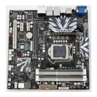
Related product manuals