nect all the power cables from the mainboard and then move the jumper cap
into the CLEAR setting for a few seconds.
C
C
o
o
n
n
n
n
e
e
c
c
t
t
i
i
n
n
g
g
C
C
a
a
s
s
e
e
C
C
o
o
m
m
p
p
o
o
n
n
e
e
n
n
t
t
s
s
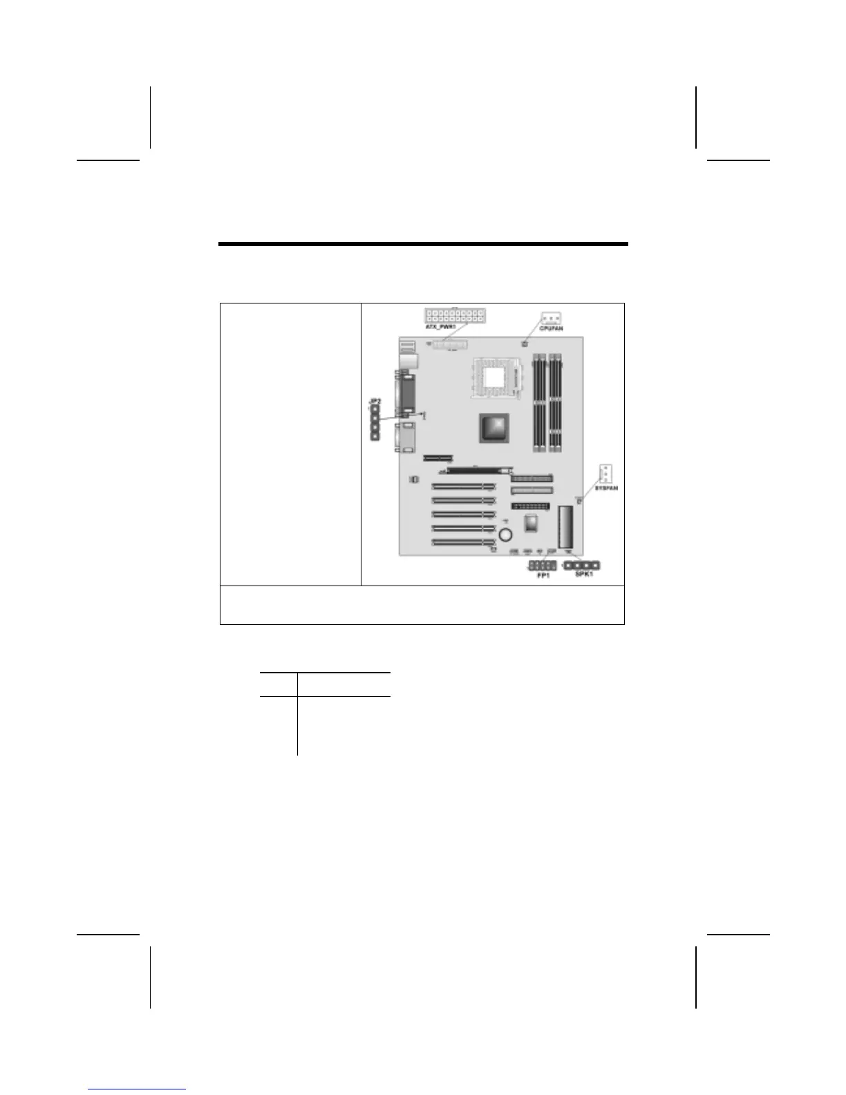
After you have installed the mainboard into a case, you can begin connecting
the mainboard components. Refer to the following:
1. Connect the power
connector from the
power supply to the
ATX_PWR1
connector on the
mainboard.
2. Connect the CPU
cooling fan cable to
CPUFAN.
3. If there is a cooling
fan installed in the
system chassis,
connect the cable
from the cooling fan to
the SYSFAN fan
power connector on
the mainboard.
4. Connect the case switches and indicator LEDs to the FP1 header JP2 for on-
board LAN LED.
5. Connect the case speaker cable to SPK1.
SPK1: Speaker Connector
Connect the cable from the PC speaker to the SPK1 header on the mainboard.
Pin Signal Name
1
2
3
4
SPKR
NC
Ground
+5V
JP2: Onboard LAN LED Connections
If you have a set indicator LEDs for the onboard LAN communication, you can
connect the LED cable to the header JP2.
Pins 1-2 are for Link LED. Pins 3-4 are for 10/100 Mbps mode LED, the on-
board LAN run in 100 Mbps mode when the LED lit.
8
 Loading...