J3A/J3B/J3C/J3D: DDR/SDR DRAM Type Selector
This jumper enables to select the type of DDR or SDR DRAM.
JP2: Wake on Keyboard/USB activity
This jumper enables any USB keyboard activity to power up a system previ-
ously in a standby or sleep state.
J13: Flash ROM Voltage (VCC)
This jumper enables to select voltage for Flash ROM.
JP4: Flash ROM Size
This jumper enables to select size for Flash ROM.
C
C
o
o
n
n
n
n
e
e
c
c
t
t
i
i
n
n
g
g
C
C
a
a
s
s
e
e
C
C
o
o
m
m
p
p
o
o
n
n
e
e
n
n
t
t
s
s
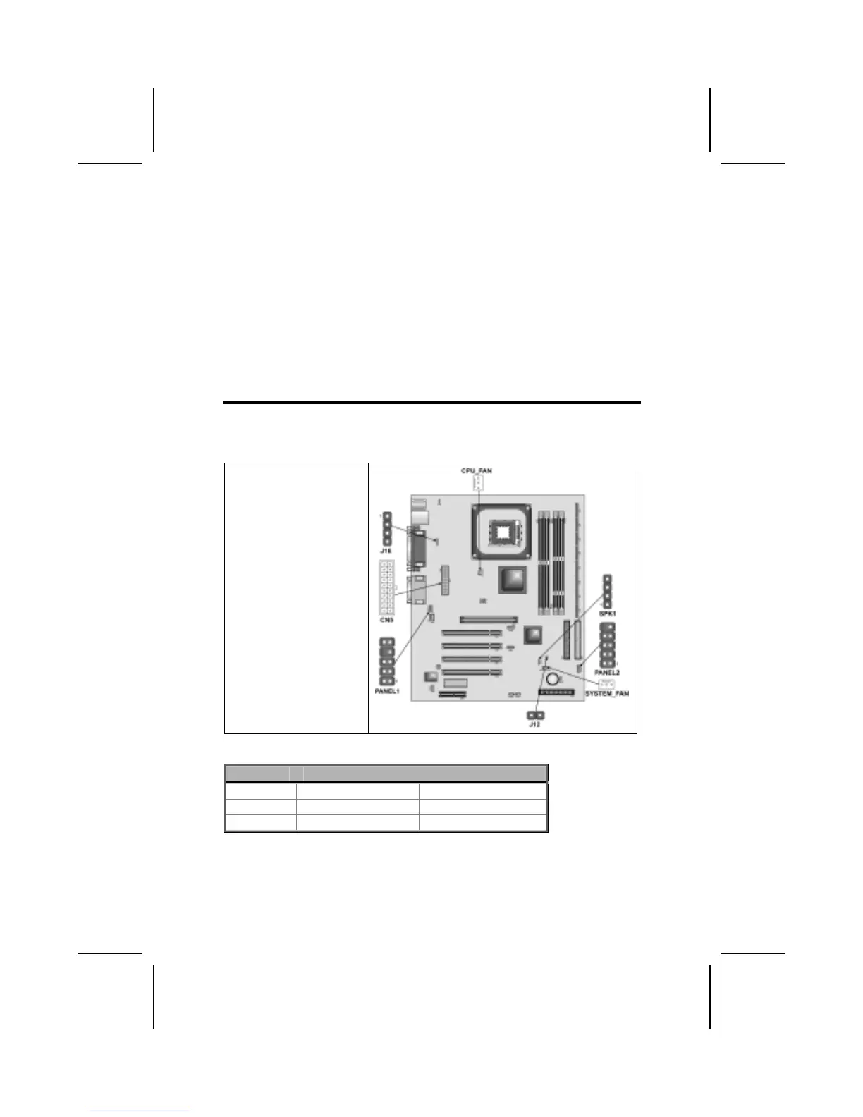
After you have installed the mainboard into a case, you can begin connecting
the mainboard components. Refer to the following:
1. Connect the case
power supply
connector to CN5.
2. Connect the CPU
cooling fan cable to
CPU_FAN.
3. Connect the case
cooling fan connector
to SYSTEM_FAN.
4. Connect the case
switches and indicator
LEDs to the PANEL1/
PANEL2 header.
5. Connect the case
speaker cable to
SPK1.
6. Connect the case
sleep switch cable to
J12.
7. Connect thecase LAN
LED cable to J16.
CPU_FAN1/SYSTEM_FAN: FAN Power Connectors
Pin Signal Name Function
1 GND System Ground
2 +12V Power +12V
3 Sense Sensor
9