CN5: ATX 20-pin Power Connector
Pin Signal Name Pin Signal Name
1 +3.3V 11 +3.3V
2 +3.3V 12 -12V
3 Ground 13 Ground
4 +5V 14 PS ON#
5 Ground 15 Ground
6 +5V 16 Ground
7 Ground 17 Ground
8 PWRGD 18 +5V
9 +5VSB 19 +5V
10 +12V 20 +5V
SPEAKER1: Internal speaker
Pin Signal Name
1 SPKR
2 NC
3 GND
4 +5V
J12: Sleep Switch
Pin Signal Name
1 -EXTSMI
2 GND
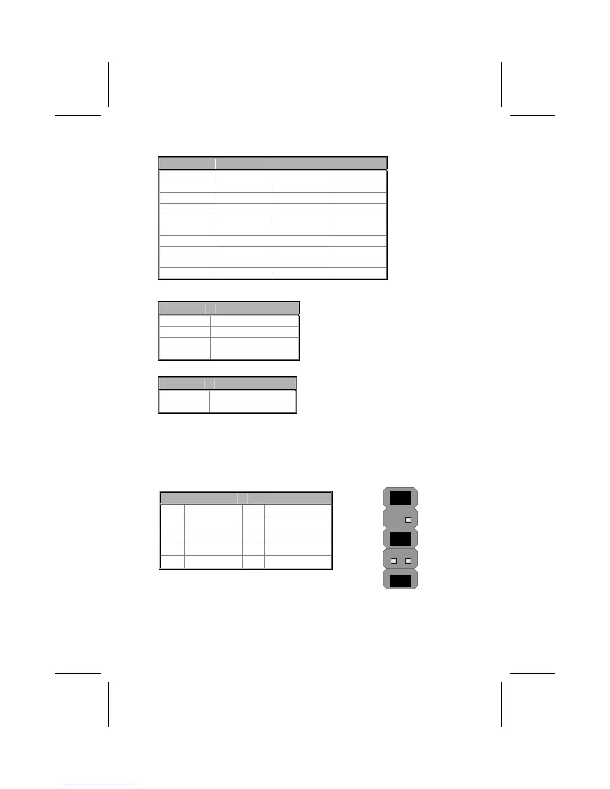
The Panel Connectors
PANEL1
If there is a headphone jack or a microphone jack on the front panel, connect
the cables to the PANEL1 on the mainboard.
Pin Signal Name Pin Signal Name
1 MIC IN 2 GND
3 VCCM 4 +5V AUDIO
5 LINE OUT (R) 6 LINE OUT (R)
7 NC 8 EMPTY
9 LINE OUT (L) 10 LINE OUT (L)
2 1
10 9
10