Technical manual C1P2FXBT – V1.7 p 8/28
2) Identification technology using the WIEGAND / Clock&Data protocol
Data sheet:
5 wires (3 pairs recommended)
0.6 mm (1/30 in) (SYT recommended)
Characteristic: Sensitive connection
Screen: Mandatory
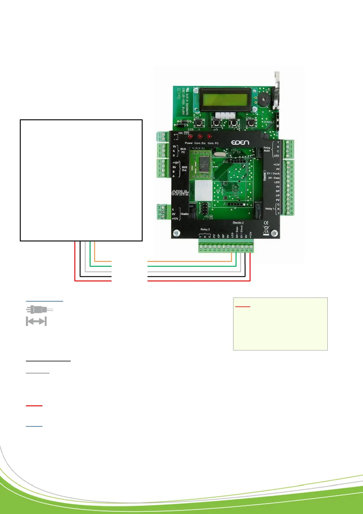
Simply connect the three wires on the reader and the power supply to the control unit terminal
block as shown.
Note: The Do not position the control unit-receiver wires close to other live or high voltage
cables, and specifically not close to 230 V cables or higher.
Note: Each reader can accept a different technology (e.g. Reader 1 in Wiegand, Reader 2 in
Clock&Data).
Note: If you use an external
power source to power your
proximity card readers,
ensure that you connect
the various earths to the
one on the control unit.
WIEGAND:
o Proximity card readers
(HID, STID, DESTEIR, INDALA,
etc.)
o Keypads (XPR, etc.)
o Biometric readers (SAGEM, etc.)
o Radio receivers (JCM, TECHNO
EM, etc.)
o DALLAS (via TMCD20 interface)
CLOCK&DATA:
o Magnetic strip readers
o Bar code readers
o Proximity card readers
o Radio receivers
LED
DATA0 / DATA
DATA1 / CLOCK
0V
+12V/100mA max