- 31 -
ENGLISH
INSTALLATION
¿g. 1 ¿g. 2
¿g. 4 ¿g. 5
¿g.
B
A
A
A
B
B
C
&
%
cm 7
cm 270
C
C
B
C
&
%
C
C
&
&
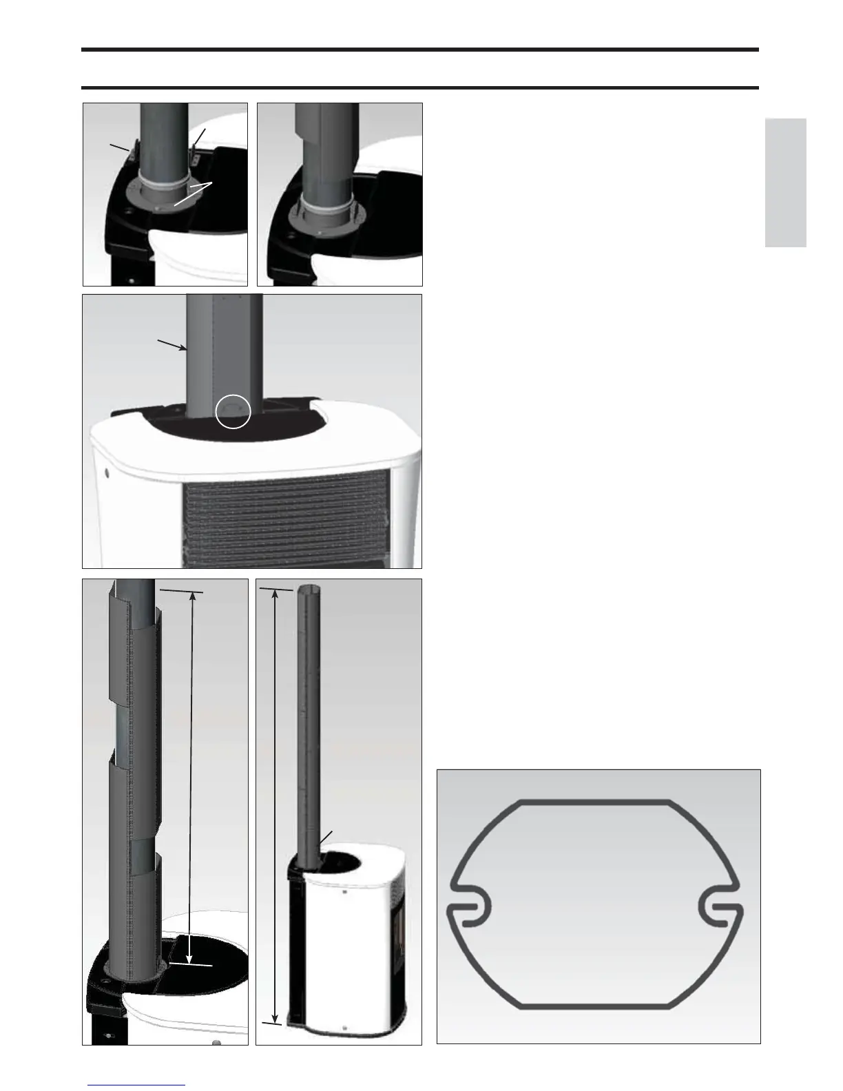
Detail of assembly of pipe cover elements
Front elements
%&
Rear elements &%
$
FLUE PIPE COVER KIT FOR VERTICAL
FLUE PIPES - OPTIONAL EXTRA (CODE
7he kit includes the following parts:
- N 1 Àue pipe ¿[ing bracket (A)
- N 2 short pipe cover elements L 25 cm (B-B1)
- N 2 long pipe cover elements L 50 cm (&-&1)
- N 8 self-tapping screws 4,2[1
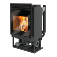
7o ¿t the kit, proceed as follows:
- Fit the pipe cover ¿[ing bracket (A - ¿g. 1) using the screws
supplied, to the two plating closers (A1 - ¿g. 1) at the holes
formed.
- 3ut a short pipe cover element on from the front (B - ¿g. 2)
and a long pipe cover element on from the back (& - ¿g. 2)
- Fi[ the bracket (A), installed previously, to the long pipe
cover element on the back (&) using screws (¿g. ).
- Fit another long pipe cover element from the front (&1 - ¿g.
4) and another short pipe cover element from the back (B1 -
¿g. 4) until a height of 8 cm is reached (equal to an overall
height from Àoor level, including the stove, of 169 cm).
- If you need to reach a height from Àoor level to ceiling of
270 cm, use another 4 long pipe cover elements (&-&1) code
761840 (¿g. 5).
 Loading...