D14643880 Issue L
Page 8 © Edwards Limited 2020. All rights reserved.
Installation
Note: It is advisable to ‘enable’ the gauge below a pressure of 1 x 10
-2
mbar since above this pressure erroneous
readings may occur. Continuous operation above 1 x 10
-2
mbar can lead to contamination of the gauge.
The signal output can be measured between pins 3 and 5. It is important to keep the signal common (5) separate from
the power supply common (2) for accurate readings.
The total source resistance of the power supply, including cabling, should be less than 50 .
CAUTION
For correct operation the Active Inverted Magnetron gauge should be connected to an earthed vacuum system.
When using a cable longer than 30 m, full compliance with European Standards requires an in-line surge suppressor
(please refer to Section 7.2.1).
3.5 Gauge set-point
3.5.1 Potentiometer adjustment
The set-point trip is adjusted by a multi-turn potentiometer accessed through a labelled hole in the end of the gauge
case. The voltage at which the trip operates can be measured with a voltmeter between pins 4 and 5 (See Figure 3).
The voltage to pressure conversion for the trip level is identical to that of the gauge signal output and is shown in
Table 1.
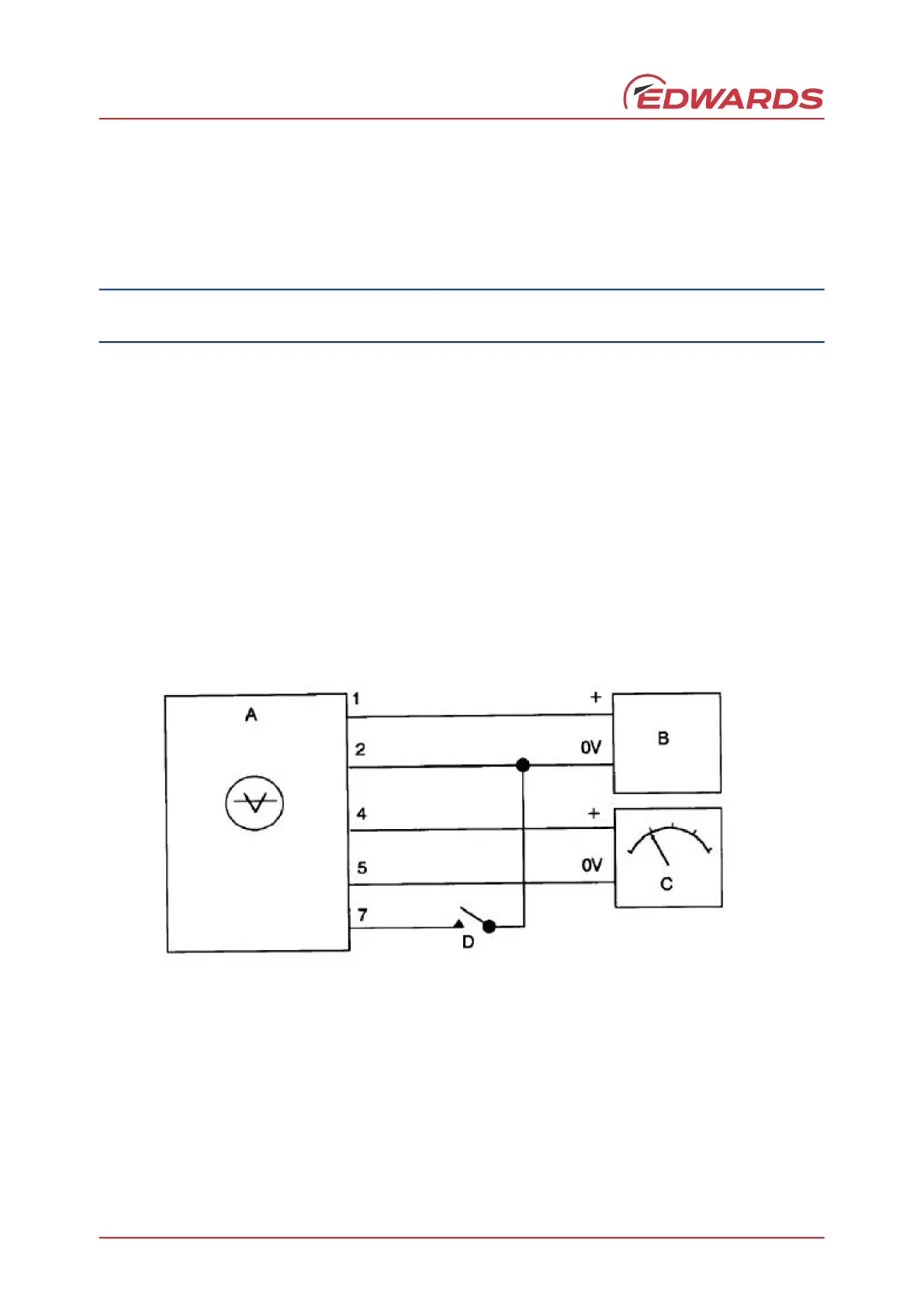
Figure 2 - Connection to power supply and voltmeter
A. Active inverted magnetron gauge
B. Power supply
C. Voltmeter or chart recorder
D. Grounding switch
E. External DC relay
F. Back EMF suppression diode
1. Positive supply
2. Supply common
3. Signal output
4. Set-point trip level
5. Signal common
6. Set-point output
7. Gauge enable
 Loading...