© Edwards Limited 2020. All rights reserved. Page 9
Installation
D14643880 Issue L
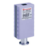
Figure 3 - Measuring gauge set-point trip voltage
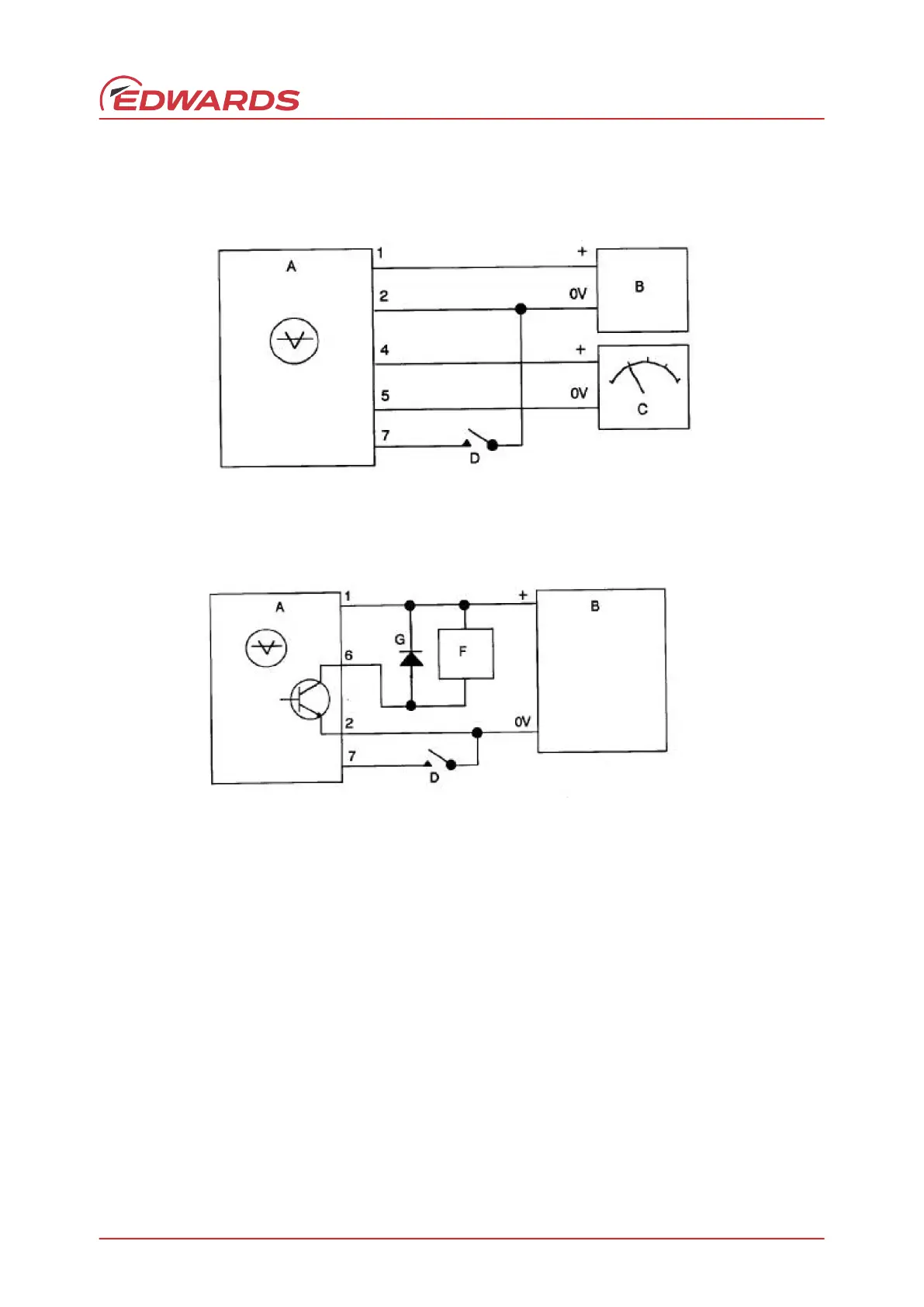
Figure 4 - Connection of relay to set-point output
3.5.2 Set-point output
Figure 4 illustrates how the open drain transistor output of the set-point should be connected to operate an external
relay (E) (refer to Key).
Note: The external relay must not exceed the ratings specified in Section 2.10.
Due to the inductive nature of a relay, a transient voltage can be generated when the relay is switched OFF. The
surge rating of the back emf clamping diode must be at least ten times the rated operating current of the relay, that
is, a minimum of 1 amp surge rating and have a minimum reverse voltage rating of 100 volts (e.g. 1N4002 diode).
 Loading...