A705-74-880 Issue K
Page 2 © Edwards Limited 2009. All rights reserved.
Edwards and the Edwards logo are trademarks of Edwards Limited.
INTRODUCTION
1.2 General description
The GV260, GV410 and GV600 pump are rugged, reliable dry vacuum pumps designed for general vacuum use.
Each pump is a four stage, positive displacement rotary pump in which three pairs of Intermeshing claw rotors and
one pair of Roots rotors are held in correct phase relation by a pair of timing-gears. The timing-gears and the adjacent
double-row angular contact ball bearings at the low vacuum end of the pump and the roller bearings at the high
vacuum end of the pump are oil lubricated.
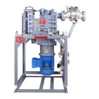
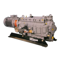
The GV pump is shown in Figure 1. The pump has lifting-bolts (5) and is mounted on a robust skidframe (9). Fixing
holes (8) in the skidframe can be used to secure the pump in its operating position.
Figure 1 - GV Pump : Key
During operation, some parts of the pump become hot; these areas are identified by 'hot surface'
labels (see Section 1.1). Do not touch these areas of the pump and avoid accidental contact
between these areas of the pump and electrical cables and wires.
Do not operate the pump with a coupling cover or blanking plates removed. If you do, there will
be a risk from exposure to rotating mechanisms.
Do not operate the pump with the pump-inlet or pump-outlet open to atmosphere. If you do, there
will be a risk from the rotating mechanisms, from the exposure to vacuum, or from hot exhaust
gases.
1. Gearbox 17. Motor terminal box
2. Cooling-water outlet 18. Arrow showing motor rotation direction
3. Temperature measurement point 19. Motor cooling fan
4. Thermal snap-switch box 20. Gearbox oil drain-plug
5. Lifting-bolt (x4) 21. Gearbox oil filler-plug
6. Pump-inlet (upper) 22. High vacuum bearings oil drain-plug
7. Temperature Control Valve (TCV) 23. High vacuum bearings oil-filler plug
8. Skid Fixing holes 24. High vacuum bearings sight-glass
9. Skid Frame 25. Sintered filter plug
10. Gas-ballast flow valve 26. Pump inlet (side)
11. Exhaust-purge port (blanked) 27. Water jacket drain plug
12. Interstage relief valve (GV410 and GV600 only) 28. Inlet gauging ports
13. Pump-outlet 29. Head plate side port cover plate
14. Gearbox: oil-level sight-glass 30. PRV purge port
15. Coupling cover 31. Shaft-seal purge inlet
16. Pump-motor 32. Cooling-water inlet
 Loading...
