A301-05-880 Issue A
Page 20 © Edwards Limited 2014. All rights reserved.
Edwards and the Edwards logo are trademarks of Edwards Limited.
Installation
Connect the supply through a contactor which has overload protection or use a controller which incorporates a
contactor.
Use a contactor that has a manual reset control. If not, the EH pump could automatically restart after an electrical
overload or an electrical supply failure.
Use a suitable multi-wire cable and a suitable cable gland (see Step 4 below) to connect the electrical supply to the
pump motor.
Connect the motor to the electrical supply as described in the following procedure.
1. Remove the motor terminal box cover (Figure 1 and 2, item 1).
2. Check the electrical supply voltage and frequency. If necessary, configure the motor (that is, the terminal wires
and any links) to operate with the supply voltage. Refer to the wiring instructions supplied with the pump motor.
3. Remove the plug from the cable entry hole that will be used for the electrical supply cable. Choose the most
suitable hole for the application.
4. Fit a suitable cable gland to the cable entry hole. The cable gland (and adaptor, if fitted) must provide a
protective seal to IP44 (or higher). Refer to Ta b l e 1 3 for the cable gland hole sizes.
5. Pass the electrical supply cable through the cable gland.
6. Connect the wires of the cable to the appropriate terminals, as shown in the wiring instructions supplied with
the pump motor.
7. Tighten the cable gland.
3.7 Check the direction of pump rotation
It is possible for the three-phase electrical supply to the motor to be phased incorrectly. If the supply is phased
incorrectly, the rotors will rotate in the reverse direction or remain stationary. Check the direction of rotation as
described below.
1. Check that the EH pump is connected to the vacuum system or that the inlet is blanked off.
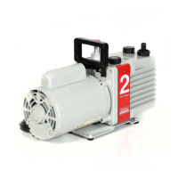
2. Connect the backing pump and switch the backing pump on.
3. On all EH2600 and EH4200 model pumps, the correct direction of rotation is indicated by an arrow on the motor
fan cover (Figure 2, item 17). To determine the direction of rotation: watch the motor fan inside the fan cover,
switch on the EH pump for two or three seconds, then switch the EH pump off.
Use the method above to determine the direction of rotation on all EH250, EH500 and EH1200 pumps.
Alternatively, the direction of rotation is also indicated by an arrow next to the direction of rotation sight glass
(Figure 1, item 10 and Figure 2, item 14): watch the motor coupling in the sight glass (Figure 8, item 7), switch
on the EH pump for two or three seconds, then switch the EH pump off.
Table 13 - Motor cable gland hole sizes
Pump type Motor frame size
*
*
As shown on the motor label.
Electrical supply cable gland
hole size (ISO)
EH pumps 90, 100 20
132 25
160 32
Blank the inlet or connect the EH pump to the vacuum system before checking the direction of
pump rotation. If not, there is a danger of objects being trapped in the rotating rotors.