© Edwards Limited 2014. All rights reserved. Page 21
Edwards and the Edwards logo are trademarks of Edwards Limited.
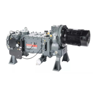
Installation
A301-05-880 Issue A
4. Check that the direction of rotation of the coupling noted in Step 3 was the same as that indicated by the
rotation arrow on the motor or on the direction of rotation sight glass. If the direction of rotation was correct,
continue at Section 3.8.
5. If the direction of rotation of the coupling was incorrect:
Switch off the backing pump and vent the system; isolate the EH pump from the electrical supply; reverse
any two of the phase wires in the motor terminal box.
Repeat the check from Step 2 to ensure that the direction of rotation is now correct.
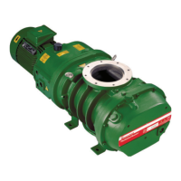
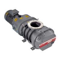
3.8 Connect the pump inlet and outlet
Connect the inlet of the EH pump to the vacuum system and connect the outlet of the EH pump to the backing pump
and exhaust extraction/abatement systems, as required.
Pump inlet and outlet connections are made with standard ISO flanges, Edwards trapped O-rings and (on the EH250FX
pumps only) an Edwards co-seal.
All EH2600 and EH4200 model pumps have two alternative outlet positions: on the underside of the EH pump, and at
the side of the EH pump.
As supplied, EH pumps are configured to use the outlet at the side of the EH pump; the flange on the underside of
the EH pump is blanked off. When using the outlet on the underside of the pump, remove the blanking plate and O-
ring from the outlet on the underside and refit the blanking plate, with a new O-ring, over the side outlet flange.
Take note of the following when connecting the EH pump to the vacuum system.
Move the EH pump to the required location and ensure that it is level and secure.
For optimum pumping speeds, ensure that the pipeline connected to the pump inlet is as short as possible
and has a bore size not less than the inlet port diameter.
Use a flexible connection in the pipeline from the vacuum system to the EH pump to reduce vibration and
stress in the system pipelines (see Section 3.2).
On very dusty applications, use a low impedance inlet filter and pump inlet mesh to minimise abrasion in the
EH pump.
Do not exceed the load limits on the pump inlet and outlet flanges as specified in Figure 9. If load
limits are exceeded, there will be a risk of leakage of process gases from the EH pump, or of
damage to the EH pump.
The EH4200 must have an inlet screen fitted at all times. Ingress of large particles can cause the
pump casing to fracture. A suitable inlet screen is shown in Table 18. If particles, debris or loose
components could enter the EH pump during commissioning or running, fit a suitable inlet filter
that can be removed before operating the EH pump on process duties.