Chapter 1: Product and component descriptions
LaserSense Nano Aspirating Smoke Detector Installers Handbook 5
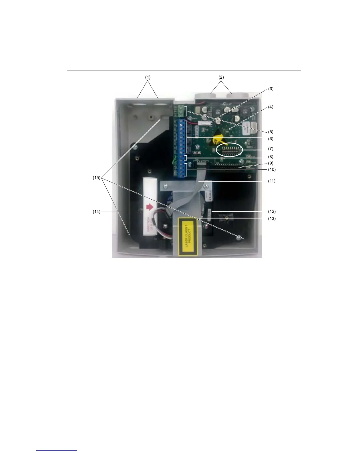
Inside the detector
Figure 2
below shows the main interior parts of a detector with the cover off.
Figure 2: Internal components
(1) Two holes for conduit connection. There are two 3/4 in. drilling guides provided on the top of
the detector and one on the bottom providing holes for conduit.
(2) Pipe entries provide a connection for 3/4-inch pipe. A 3/4 in. male to 25 mm female adapter
is required when using larger than 1 inch (27 mm) O.D. pipe.
Note: Do not glue pipes into the detector to allow for future removal.
(3) Aspirating fan connector lead: If this lead is broken or not connected, the fan will not turn and
the detector will indicate a FLOW fault.
(4) Main PCB: No user-serviceable parts.
The PCB is fixed in place with 5 M3 x 6 screws. The detector should not be operated with
any of the screws missing, as this could cause air leaks and unreliable operation.
(5) Power supply connection terminals
(6) Volt-free relay contact terminals
(7) DIP switch: Used to configure user-selectable detector functions.
(8) Input switch terminals
(9) Ribbon cable connection for optional communication card or APIC card
(10) Optional communication terminals: used when the optional communication card is fitted to
connect the RS-485 network
 Loading...