Chapter 2: Installation and configuration
22 LaserSense Nano Aspirating Smoke Detector Installers Handbook
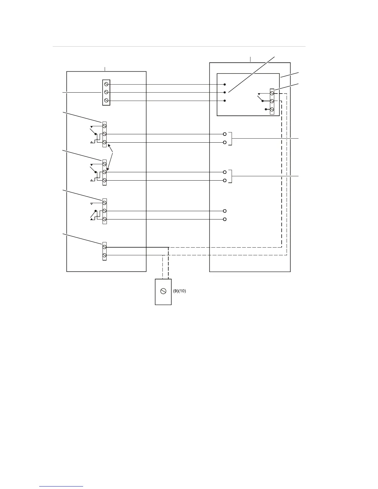
Figure 11: Wiring diagram
+24V
(16)
0V
(1)
(15)
NC
NO
C
(13)
(12)
NC
NO
C
NC
NO
C
NC
NO
C
(3)
+
–
(5)
(6)
(7)
(8)
(2)
(4)
(11)
(14)
NC = Normally closed
C = Common
NO = Normally open
(1) Detector
(2) Fire alarm control panel (FACP)
(3) Ground
(4) Power supply unit (PSU)
(5) Opens on power failure
(6) Short will indicate Alarm
(7) Short will indicate Pre-Alarm
(8) PSU fault monitoring (DIP switch 7 to OFF)
(9) Key switch
(10) Short to reduce sensitivity by 50% (DIP switch 7 set to ON)
(11) Input
(12) FAULT
(13) PRE-ALARM
(14) EOL resistor must be placed at last daisy chained detector
(15) ALARM
(16) Earth
 Loading...