© Edwards Limited 2012. All rights reserved. Page 19
Edwards and the Edwards logo are trademarks of Edwards Limited.
Connection for serial control and monitoring
A735-01-860 Issue A
3.9.2 Decoding service status word
The service status may be accessed directly via the serial link. This method of accessing service status will give the
most complete picture of current and future service requirements and will allow preventative maintenance activities
to be scheduled.
A summary of the current pending service status is provided in response to the service status command:
You will receive the following reply:
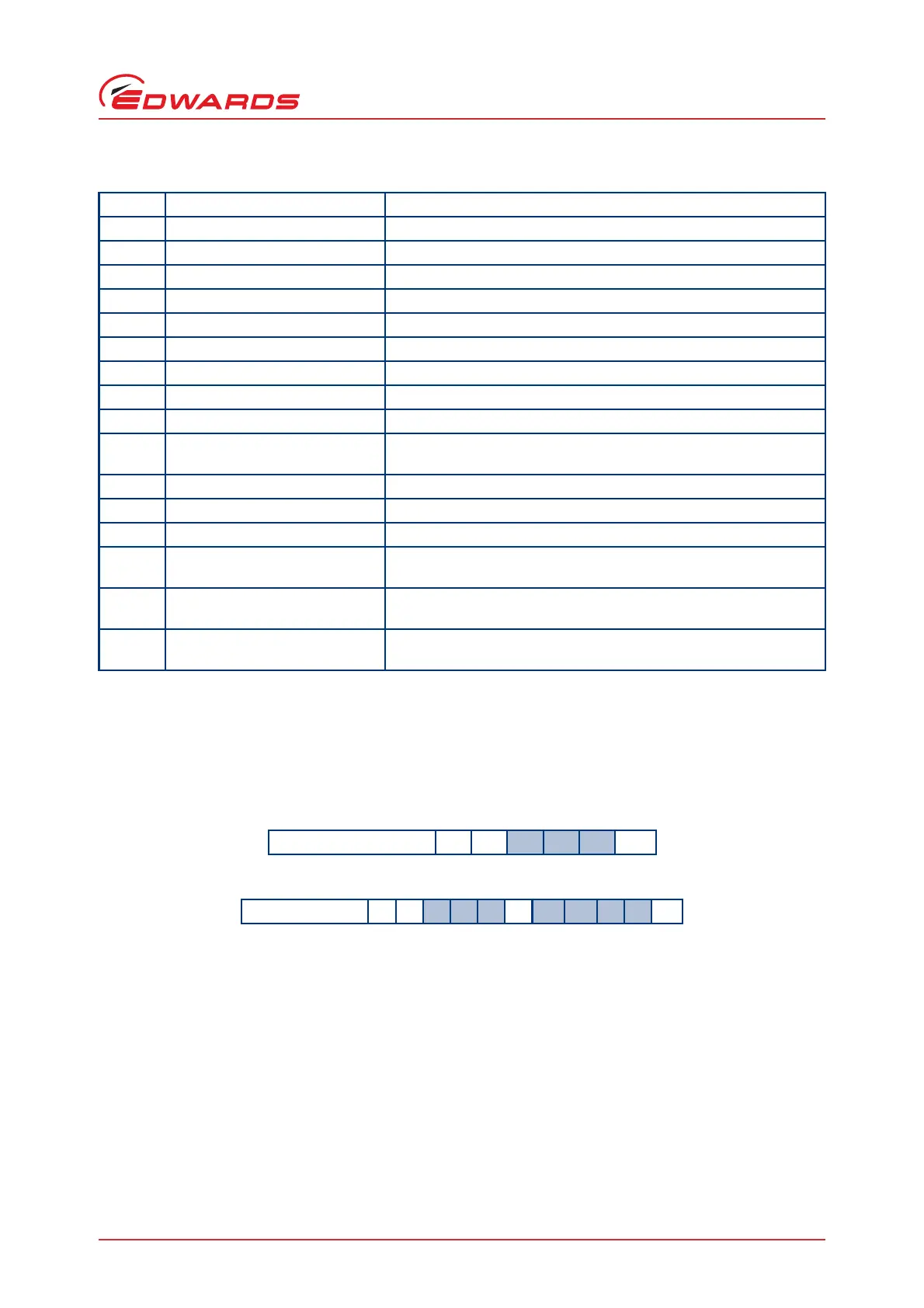
The service status word is made up of 4 hexadecimal digits. To decode this word, you must convert each hexadecimal
digit into a 4-digit binary number as described in Section 3.9.1.
Each binary digit (bit) represents a flag that is either active (state 1) or not active (state 0). To help decode the
service status word, each bit is numbered (starting with 0 for the least significant to 15 for the most significant) as
shown in Section 3.9.1. The meaning of each bit in the service status word is given in Table 11.
Table 10 - Fault register flags
Bit Status Flag Active Flat Meas
0 (lsb) Reserved -
1 Over voltage trip Fault due to excessive link voltage
2 Over current trip Fault due to excessive motor current
3 Over temperature trip Fault due to excessive pump-controller temperature
4 Under temperature trip Pump-controller temperature sensor failure
5 Power stage fault Power stage failure
6Reserved-
7Reserved-
8 H/W fault latch set Hardware fault latch active, see bits 0-7 for detail
9 EEPROM fault Fault due to a critical EEPROM problem (e.g. Parameter upload
incomplete)
10 Reserved -
11 No parameter set Parameter set upload required
12 Self test fault Self test fault (e.g. Invalid software code)
13 Serial control mode interlock Fault because the serial enable input went inactive whilst operating
with a serial start command
14 Overload time out Fault because the output frequency fell below the threshold for
more than the allowable time (with an active start command)
15 (msb) Acceleration time out Fault because the output frequency did not reach the threshold in
the allowable time (following a start command)
Command ?
V 8 2 6cr
Reply = V
8 2 6sph h h hcr
 Loading...


