A732-01-880 Issue D
Page ii © Edwards Limited 2018. All rights reserved.
Contents
5.7.2 The pump has failed to achieve the required performance ..................................................... 22
5.7.3 The pump is noisy ...................................................................................................... 22
5.7.4 The pump surface temperature is high ............................................................................. 23
5.7.5 The pumping speed is poor or if pump down time is too long................................................... 23
6 Storage and disposal ............................................................................ 25
6.1 Storage ................................................................................................................... 25
6.2 Disposal .................................................................................................................. 25
7 Service and spares............................................................................... 27
7.1 Introduction ............................................................................................................. 27
7.2 Service ................................................................................................................... 27
7.3 Accessories .............................................................................................................. 27
7.3.1 Electrical cables ........................................................................................................ 27
7.3.2 Silencer................................................................................................................... 27
7.3.3 Gas ballast adaptor..................................................................................................... 27
7.3.4 Solenoid operated pipeline valves ................................................................................... 27
7.3.5 Tip seal and exhaust valve service kit............................................................................... 28
For return of equipment, complete the HS Forms at the end of this manual.
Illustrations
Figure Page
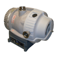
1 XDS100B scroll booster.................................................................................................. 3
2 Performance characteristics ........................................................................................... 6
3 Installation drawing .................................................................................................... 11
4 Logic interface schematic............................................................................................. 18
5 Inlet strainer assembly ................................................................................................ 21
Tables
Table Page
1 Operating and storage conditions ..................................................................................... 5
2 General characteristics ................................................................................................. 5
3 General mechanical data............................................................................................... 6
4 Electrical ratings for continuous operation.......................................................................... 7
5 Recommended regional supply protection........................................................................... 7
6 Recommended cordsets ................................................................................................ 7
7 Pin status on the logic interface connector ........................................................................ 18
8 Maintenance plan....................................................................................................... 20
9 Solenoid operated pipeline valves ................................................................................... 28
 Loading...
