Electronic device DMU2000 - DMU3000 - DMU3000 PLUS
Electronic device DMU2000 - DMU3000 - DMU3000 PLUS
45
4
7
1
3
2
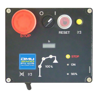
E) When starting the DMU, the warning lights 1, 2, 3, 4,
and 7 are flashing quickly and
a continuous acoustic alarm is emitted Biiiiiiiip
CAUSE
The DMU receives the indication that a crane control bank lever is not in its central position: a micro-
switch tted behind a control bank lever is operated in both direction.
! FAILURE ANALYSIS
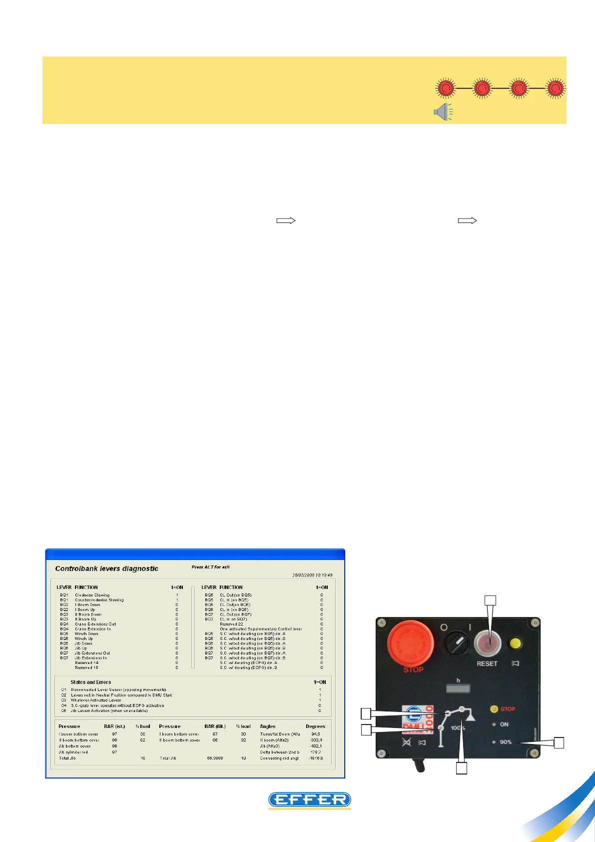
If the computer is connected to crane (tools control bank lever diagnostics conditions and
errors) three errors are displayed:
- “1” appears next to: lever sensor disconnected (contrasting manoevres)”
- “1” appears next to: “lever not in neutral position when DMU is started”
- “1” appears next to: “any one lever operated”
The indication “1” on BOTH directions of a lever appears, (a lever of control bank is operated in BOTH
directions)
CHECK
Check the error state disappears on computer when carrying out the electric by-pass on microswitch
connecting cable, as outlined in Chapter 17. If the error state does not disappear, this means that the
electrical connecting cable is interrupted between the DMU and the microswitch.
SOLUTION
Restore electric connection.