Z Series Assembly Manual
© 2023 EFT Electronic Technology Co. Ltd. All Rights Reserved.
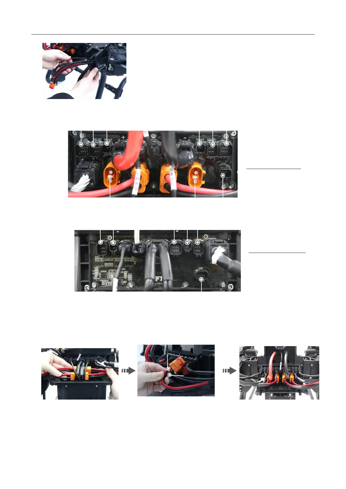
3. Please check the pins of each interface before wiring, and connect t hem correctly according to the label to avoid wrong insertion.
4. Arrange the internal cables, make sure that the power transfer cable on the l eft of the front cover is connected with the m otor
cable on the right, and the power transfer cable on the right is connected with the left m otor cable, and then plug the 4 power cables
into the rear circuit board.
Note: *W hen installing the power cable, Up is the positive pole [ red positive, black negative].
5. Apply grease to the sealing ring of the signal plug, and in sert them into the corresponding positions according to the marks.
Note: Do not skew when plug ging in. I f it cannot be inserted, you n eed to check whether the internal pin s are bent or wrong port.