L'll
'A|Jad01d 5U!18J9dO
f(,,s>|og|o,,
LL01!/v\s aql
|!1un
sL1! 1eq1
ems A|qeu0sea1
aq ueo auo ’pa1eogpug
se pauuo;
uml)
as;/v\>|00|01e1un0:> A||n; :'|eQ !QLx zugeg (2)
-19d
luawmlsug
aql 4|
's>|oaqo Leglgug
aqn, sa1a|dwoo
s!|.|_|_
:s6ug11as
|OJ1UOO Leglgug 6uL/v\0||0,1 aL|1 e>|e|/\L
(g)
'uog1gs0d
(1no) :|:]Q
aql 01 L|C)1!N\S J9MOC|
eql
umlag (ZL)
'suog1gs0d
qloq
10;1q5;|
'1!un
01 1Lun
p|n0qs JO1BO[pU! uaa16 aqi '1q5[J aql 01 1; qsnd uaql
u101;
A|qe1ap!su0:>
Me/\ uea
apn1!|dwe Leugs
a1n|0sqe
‘1;a|
9L|1 01 a|6601
1sa1 Malleq
pepe0|-Bupds
9141 qsnd
(17)
8L{1
'.l9A8N\O|-| '/\LLl
Q9 A||e0gdA1
‘|a/\a| /v\o| e 01 aseamap
p|n0qs
1nd1n0
9l.|1 fu011nq
Me/\00a1
"L/\() aql sseud (LL)
'p8SS9Jd8p
sugeweu 1g1eq1 os qf)1!N\S J8IV\Od aql ssc-ud (3)
'>|d->|d
/\ L aq p|n0qs
La/\a| 1nd1no sq), f1nd1no
aql
'G|OQld9I)9J
J9N\Od
aql o1uL
101Lu0|/\|
'>|d->|d /\ L ‘z|_|>| L 01 JO1BJ8U95
Leugs aql 1a3 (QL)
pue 1uaLum1suL
aq),
L0 1291
sq),
01u! p100 aug| sq], 6n|d (3)
-lam‘
lndu!
QZZ
JO
oe /\ 9L L) pasn aq 01 a5e1|0/\
au|| sq), 6u|1L2(:>O|iJ:1\|
d
f d
.
.
. .
aql
sawp,
ua1 aq p|n0qs
La/\a| 1n
1n0
aql
1n
1n0 9141
JO1!u0W_>|d_>|d
,ZH
Jolejaua
‘Bums
(6)
uoglgso sq), ug sq
LL01!/v\s
ap!|s Laue -ma; 8L|1 ems
a>|e|/\|
(L)
ElH(]3OOHd 8'2
'>|d->|d
/\ L
eq
p|noqs
La/\a| 1nd1n0
aqa,
51nd1no
aql
101guo|/\|
(3)
'z|-|>|
L
pue ‘z|_|
QQL ’z|_|
L12 a/\e/vxaugs
>|d->|d
/\ L e
Bugpg/\01d
L0
a|qedeo JOlB.l9U95 |eu6!3
(Z)
('s6ugpea1
1nd1n0
pue
sumas 1ndu|
uaa/v\1aq
A:>ua1s|suoo
u|e1q0
01 ‘s6u|11as
edoasomaw
Molejoqm
asodmd ‘mama
(L)
apn1!|du1e
.|01e1aua6
|eu5gs aql
a>Leu1
01 ad0os0||g:>s0
3l.|l
asn)
'>|oe[
;)|\|g lndug
V
8L|1
01
1!
loauuoo
CHCHQN
-|-N3Wd|nO3
Z2
pue
'>|d->|d
A
L
IZH
L
01 1o1e1aua6
|eu6gs aql
19$
(L)
wmleluasajdal
aql 1oe1u0:) ‘s>|oaqo asaql 1n0 Bug/X11129 ug pa1a1uno:>ua
aq /\1|n:>g;Lgp Aue p|OL|S
'/\||Q1U£-)LU!.l9dX9
15 Bugsn a1o;aq 1nq
'(U0!1B.lOd.lOQ
qomasag pauddv uolaoupd 01 pue J9!.lJBI)
aq1
01 panodaj aq 01 palou Aue) aewep Bugddgqs 10; luau;
'ZH>|
L
Il0J1U09,l,l0||OH
/\:>uanba1:L
q5!|_|
(p)
-nnsug
amp,
ugmadsug Jaye pauuopad
aq p|noqs
ampaoojd
aqn,
’|e1aua6
u| 'gLL |ap0|/\|
aql Lo 5U!>|38L|3
a0ueuu0,uad
'z|-L L
1|OJ1UO1)HO||OH
Aou:-)nba1;L
/v\0"|
(0)
l9!1!U! 9191!|!99}
01 P9P!'\0Jd 5! 9mP99°1d 5“!/\/\°||°} 9LLL
'>|oe[
3N9
1nd1n0 aql
01 ado0s0||!:)s0
aql
laauuog
(9)
'c1|\|91ndu!
s‘:)v1ndu!v =5u!|dn<>:> (q)
NOLLOHCJOHLNI
L'Z
S)lO3H3
'lVl.l.lNI
ll
NOLLOHS
SECTION
II
INITIAL
CHECKS
2.1
INTRODUCTION
The
following
procedure
is
provided
to
facilitate initial
performance
checking
of
the
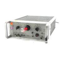
Model 113.
In
general,
the
procedure
should be performed
after
inspecting
the
instru-
ment
for shipping damage (any
noted
to
be reported
to
the
carrier and
to
Princeton Applied Research
Corporation),
but
before using
it
experimentally. Should
any
difficulty be
encountered
in carrying
out
these checks,
contact
the
factory
or
one
of
its representatives.
2.2 EQUIPMENT NEEDED
(1) General
purpose
laboratory oscilloscope.
(2) Signal
generator
capable
of
providing a 1 V pk-pk
sinewave
at
1 Hz,
100
Hz, and 1 kHz.
2.3 PROCEDURE
(1) Make sure
the
rear-panel slide switch
is
in
the
position
indicating
the
line voltage
to
be used
(115
V ac
or
220
Vac).
(2) Plug
the
line
cord
into
the
rear
of
the
instrument
and
into
the
power receptacle.
(3) Press
the
power switch so
that
it remains depressed.
(4) Push
the
spring-loaded
battery
test
toggle
to
the
left,
then
push
it
to
the
right.
The
green indicator should
light for
both
positions.
(5) Make
the
following initial
control
settings:
(a) Gain:
x10;
Cal.: fully counterclockwise
(turn
until
the
switch
"clicks").
11-1
(b) Coupling: A
input
AC, B
input
GND.
(c) Low
Frequency
Rolloff
control:
1 Hz.
(d) High
Frequency
Rolloff
control:
1 kHz.
(6)
Connect
the
oscilloscope
to
the
output
BNC jack_
(7)
Set
the
signal
generator
to
1 Hz, 1 V pk-pk, and
connect
it
to
the
A
input
BNC jack. (Use
the
oscilloscope
to
make
the
signal
generator
amplitude
settings,
to
obtain
consistency
between
input
settings
and
output
readings.)
(8) Monitor
the
output;
the
output
level should be 7 V
pk-pk.
(9)
Set
the
signal
generator
to
100
Hz, 1 V pk-pk.
Monitor
the
output;
the
output
level should be
ten
times
the
input
level.
(10)
Set
the
signal
generator
to
1 kHz, 1 V pk-pk.
Monitor
the
output;
the
output
level should be 7 V pk-pk.
(11) Press
the
OVL
recovery
button;
the
output
should
decrease
to
a low level, typically
50
mV. However,
the
absolute signal
amplitude
can vary considerably
from
unit
to
unit.
(12) Return
the
power
switch
to
the
OFF
(out) position.
This completes
the
initial checks. If
the
instrument
per-
formed
as
indicated,
one
can be reasonably sure
that
it
is
operating properly.