L‘/\
'z|-|
QQ17
'su0g1gsod
@ (Annexe)
/\ 1 01 e6e1|0/\ sgw aql 1sn[pv 'apn1g|dwe
pun016 .l!8L|1
01 saqalg/v\s
6ug|dn0o
lndug
qloq
lag
(L)
|eu6gs a1.|1 aueqo
p|n0/v\ 1,2141 maoo
1ou saop peo|
;o aueqo
2 leqa, os JO1BJ8U85 |eu6!s
aql
01 paloauuoo TGV NO“-QHPBH 360'/WNQWWOQ 93
ugewm lsnw JO18l1Ll311B
aql 5Ja1aLu1|0/\
suu uogsgoeud
aql qlg/v\ J01E’J3U35
|eu6gs sq],
,10
1nd1n0
aql 101gu0|/\|
'(|B=>)
>1 Z
01
H91!/V\$ W95)
QLI1 19$
PU?
'O(] °l LI°1!'V\$ HQIIOH
:|"l
'ZH>|
O08 01 L191!/W5 HQIIOH
:lH QLI1 '(]NE) 01
H91!/\/\$
5U!Id"°9
Q_8L|1
'Q(]
01
qcng/v\s 6ug|dn0:>
lndug V s,gL1 aql lag
'1ndug
V s,g[L
|apo|/\|
aql 01 101enua11e
aql ;0 1nd1n0 aql loauuoo
pue ‘1o1e1aua5 |eu6gs
8L|1 ;o
1nd1no
aqm,
01 1o1enua11e lzgggz I-)L|1 1:>euuo3
<2)
‘ '
(Z)
m
1'“ ""“‘
'1a1euu1|0/\
up
9L|l
qlg/v\
Q|\|g1nd1n0 aql 101gu0|/\|
(3)
'pea|-dg|o aL|1
anoweg
gm
'(/\W
Z1)
/\ O
104 LLZH
1‘5"[PV
H71’
‘VOL 01
u¢>1!~\s we
aul
ws
(zl-
qzng/v\s
aql
1e
1oauuo0£punoJ6
01 1401!/v\s
;;,o||0H
40
.l9d!M aql
loauuoo
01 pea-9|-d!|o uoqs
e asn (L)
Nollvaanvo NW9 9.g
TCIV
OHEIZ
EIOHHOS ELLVE)
.LEl:I ZV V9
'uog10a[a1 apow-uowwoo
wnwgldo
Jo; sawp,
|9.l9l\9S 91 L{5n0.lL|1
()1 sdals
leadag
(LU
'31E‘.lC)3B
%['Q
‘[:()[
pue
[IQQQZ
’sJo1enua11v
(9)
'xew /\ ZL '1nd1n0
5ug1eo|;
‘A|ddns op a|qeg1e/\
(g)
n
6
d I
'00l
01
W95
Ell
I9P°/\| QLI1 198
'z|-|>|
90$ ‘>|d->|d
/\
Z 01 10191:-aua
|eu6gs aq1 1sn[pv
'ado:>so||gos0
U0 ZH>l
00L W"W!U!W 1°}
9lLO PUB
QOLI) 15n!PV
'(1nd1n0
aql
01
paloauuoa
||!1s) adoos0||g0so
aql uo
Ae|dsgp
e uge1qo 01 /uessaaau
se uge
aql lsnfpv
'ZH>l ODS 91
|°J1U°9
HOIIQH
:lH
9Ll1 198
'z|-|>| QQL ‘>|d->|d
/\
Z 01 1o1e1aua6
|eu5!s sq], lsnfpv
'9dOOSO||!OSO
SL1}
Aq p81BO!pU! SB
‘ld
-mo
ZH
00LllJnll1!U!W
1<>4("rc1v HWC))8LLH19"!PV
'ZH>|
L01 L191!/V\$H°|l°H
:lH
BLI1 19$
(SH
"13 0017
|@p<>v\| P1@>1v@d-11@|M@H
SB
L|OS '919JnOOE
%['Q 'J319lLll|O/\ SUJJ UO!S!O8.ld
(em) ‘ pug
'u0g11o1sgp
/v\o|
’a5ue1 2|-|>|
Q09
'JO1BJ9U95
a/\e/v\au!g (L)
(ZL)
(ll)
"A1!/xglgsuas uua//\Lu
asuodsa1
Aouenbw;
z|_|>|
Q99 '3dOOSO||[OSQ
(Z)
c1ac1z|2||\|
J.NElWdlOE|
2'9
'1U9lUU5[|B Bugmp pue aJ0;aq s>|oaqo |eu6gs
pue a6e1|o/\
alepdmdde
aql
5U!>|9LLl
Aq
S!L|1
40
ems
e>|ew
p|OL{S LlB[Z)!UL|O€-)1
8L|_|_ "e/\g1oa;ep we
luawnnsug
eql
ug sluau
-oduuoo
ou 1eq1 sawnsse
empaomd 1uaLuu6g|e
sgqi :3_|_Q|\|
‘[6]’
1:8)
'1U9LUJ1SU[ 8L|l azg61aua pue
J8/V\0d
eu!|
oe
eql
10:-)uuo:> ueq_|_ '(|eued
JBGJ
apgsug
uo pa1eo0| ‘u0g1e1ad0
A
OSZ 1°} V ZS/L 1°
U°!1919d° /\ Qll 1°} V 9L/L)
P9ll91$U!
was sg
asn;
aug|
azgs
J8dOJC| 9L|1 ems
eq pue
’pasn aq 01
a6e1|0/\
' ' ‘ ‘ aug|
8L|l Bugleagpug
uoglgsod
aql
up
sg qolg/v\s
|8UBC|-188.1
'Q(] 01
saqoll/v\s
6u!|dno0
lndug
qloq
leg
'19)
aql ems e>|ew '19/V\OC| aug| 02 u.10J; 5U!1€J9dO aJ0;ag
'(8pOLU
uou1u1o0)s1ndu!
3 pue
.
/\»HVN|W|_|3Hd Z-9
(9)
.HA
6 A - d 6 d
_SdO1S uogloag ug wen egp 1n0 e| pmoq lgnrngo a|.|1 pue q 91
olou
. II.
Ll
.
d A I I , d aql
01
.l8].8J uogloas sgq1 ug pauogluaw
s1u!0d1se1
pue
1ug0
8L|1
puo aq 1sn_
01 0033 1sn_pe
1uasa1 sg uop, 5 6
S1U8UO
WOO U!1BOO JO O18 UO
9 lU9UOC|UJOO 9 1
1|nO.l!O
—e"!QS0 adoasomoso eul q1!M lndlno aql JOHUOW 19L}/V\ U0 5UlpU9d8p
I’/\.lB:iS9O9U Gql
/3911.1 1U9lJJU5||€‘:1.l8I\.8/\/\OL|
UN8
lndlno
am
‘paae|de1
sg
wauodwoa
e ;| "as!/uas aeu;-a|qno11
a/\g6
1e
sp /\
Q Jo; |o11u0o
01a2
op |aued
1u01;
9l.|1 1sn[pv
(3) P|"°LI'5
L|9!LW\ luawmlsul
9|q9!l91 '9|q91$ 9 5!
SILL
IBPOW
QLLL
V GL|1
O1
|8U5!S 8/\BM9U!S
ZH
>‘|d->|d /\ 17 B
1-QGUUOQ
‘SCI
01 L191!“/\$
HQIIQH ;|‘|
9H1
198
(Z)
NOl.|.O(]OH.LNl L'9
3!:lCl3DOHd .l.N3INNBl'lV
l\ NOLLDHS
SECTION V
ALIGNMENT
PROCEDURE
5.1
INTRODUCTION
The Model 113
is
a stable, reliable
instrument
which should
give
trouble-free service.
If
a
component
is
replaced,
however, alignment may be necessary, depending on
what
circuit
the
component
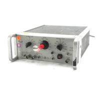
belongs to. For locating
components
and
testpoints
mentioned
in
this section. refer
to
the
photograph and
the
circuit-board
layout
diagram
in
Section
VII.
5.2
PRELIMINARY
Before operating from ac line power, make sure the
rear-panel switch
is
in
the
position indicating
the
line
voltage
to
be used, and be sure
the
proper size line fuse
is
installed
(1/16
A for
115
V operation
or
1/32
A for
230
V
operation, located
on
inside rear panel). Then
connect
the
ac line power and energize the instrument.
NOTE: This alignment procedure assumes
that
no compo-
nents
in
the
instrument
are defective. The technician should
make sure of this by making
the
appropriate voltage and
signal checks before and during alignment.
5.3 EQUIPMENT NEEDED
(1) Sinewave generator,
500
kHz range, low distortion.
(2) Oscilloscope,
500
kHz frequency response and
mV
/cm
sensitivity.
(3) Precision rms voltmeter, 0.1 % accurate, such as
Hewlett-Packard Model
400
EL.
(4) Dc voltmeter, capable
of
measuring 0 V
to
within 1
mV, and capable
of
measuring
11
V
to
within
50
mV.
(5) Variable
dc
supply, floating
output,
12 V max.
(6)
Attenuators,
2000:
1 and 10:
1,0.1%
accurate.
5.4 A2 FET GATE SOURCE ZERO ADJ.
(1)
Use
a
short
clip-lead
to
connect
the
wiper
of
the
HF
Roll
off
switch
to
ground;
connect
at
the
switch.
(2)
Set
the
Gain switch
to
10
4
•
(3) Monitor the
output
BNC with
the
dc
voltmeter.
(4) Adjust R211 for 0 V (±2 mV).
(5) Remove the clip-lead.
('
5.5 COMMON-MODE REJECTION ADJ.
(1)
Set
both
input
coupling switches
to
their
ground
positions.
V-1
(2)
Set
the
LF Rolloff switch
to
DC.
(3) Adjust
the
front
panel
dc
zero control for 0 V
dc
at
the
output
BNC.
(4) Monitor the
output
with
the
oscilloscope.
If
oscilla-
tion
is
present, adjust C200
to
just
beyond
the
point
where oscillation stops.
(5)
Connect
a 4 V pk-pk
100
Hz
sinewave signal
to
the
A
and B inputs (common mode).
(6) Set both
input
coupling switches
to
DC.
(7)
Set
the
gain switch
to
10k.
(8)
Set
the
HF
Rolloff switch
to
1 kHz.
(9)
Adjust
R118
(eMR
ADJ.) for
minimum
100
Hz
out-
put,
as
indicated
by
the
oscilloscope.
(10) Adjust
the
signal generator
to
2 V pk-pk,
100
kHz.
(11)
Set
the H F Rolloff control
to
300
kHz.
(12) Adjust
the
gain
as
necessary
to
obtain
a display on
the
oscilloscope (still
connected
to
the
output).
(13) Adjust
Cl05
and
Cl16
for minimum
100
kHz
on
oscilloscope.
(14) Adjust
the
signal generator
to
2 V pk-pk,
300
kHz.
(15)
Set
the
Model
113gaintol00.
(16) Adjust
C1
08
for minimum signal
output.
(17) Repeat steps
10
through
16
several times for
optimum
common-mode rejection.
5.6
GAIN
CALIBRATION
(1) Connect the
2000:
1
attenuator
to
the
output
of
the
signal generator, and
connect
the
output
of
the
attenuator
to
the
Model 113's A input.
(2)
Set
the
113's A
input
coupling switch
to
DC,
the
B
coupling switch
to
GND,
the
HF Rolloff switch
to
300
kHz, LF Rolloff switch
to
DC,
and
set
the
Gain switch
to
2 k (cal).
(3) Monitor the
output
of
the
signal generator with
the
precision rms voltmeter;
the
attenuator
must
remain
connected
to
the
signal generator so
that
a change
of
load does
not
occur
that
would change
the
signal
amplitude. Adjust
the
rnis voltage
to
1 V (exactly) @
400
Hz.
 Loading...