L"/\|
-gsod
L|Ol[lV\S
uge
||e 101 sLuq0|g>| 5'91) 1gn:u!:>
JO1BnL1911B
HJ.Vd
mauuno
d00'l-C|NnOu9
‘L-Al
@1"5!=l
uge
aq1
Aq pa1uasa1d
aoue1sgsa1 sagas
aq1
10 pesodwoo sq
1e1|!111o||01 :||_| aqi '1a1|g1 Bugpuodseuoa aq1 10 A:>uanba11
11o||o1
qoee 101 s101g0ede:> 1ueJa11gp
1oe|es
saL|01g/v\s
110||01
(dO°3°fng§‘a"l%§§)
zn pug IIH aqi wepuel
U!
pawauuoa
Slam}
DH
9|dw!S
GNHOHSHSISSVHQ
W3
0Nn0a9as|ssvH:>
we s1!n01g:>
11o||o1 Aouanbeq
/v\o|
pue
/\Quanba11 qgq
eqi
X @39nON' fX
~ @
~
~
LIHOHIC) H3.L'll:|
:l:lO'l'lOH GL1?
1~3aano
' dOO‘1 CJNHOUQ
'1!n01g:>
>|:>eqpaa1S!L|1
ug
0s|e
sg ‘UH
’1e!u1a/\ uge
aq_|_ 'Q()[_X
VOI
01 uge
9L|1
aseanug
01 L3 10 u0g10as 2|
eL|1 Aq
ug
paqcug/v\s | l
-
N N
sg '()[_H pue 55
6U[S[.ldLUOO 'JO1B|'\U8llB
1:01
J8L|1OUB | a
~
~
'
suog1gsod
aeu:.|1
1se|
eq1 u|
'Q[ 1see|1e1o
uge e
q1g/v\
91E‘.|9dO
ZV S8>|QUJ ZV10 1ndug 6ug11e/\ug a|_|1 1e
101enua11e >|oeqpee1
Q“ BOON T (ONHOHS WNSISD
LUL|O|!>| 9'17-Luqo Q99 eL|1 'suo!1gs0d
1491!/v\s-uge
He
10:; H
'suog1gs0d
q:>1g/v\s
||e
1o11gn91g0
HOIIQJ
9Ll1 01 99U9P9dW! W195
W1
Sluesald
1°19nu9119
1ueog1!u6gs
V 'o1e
's1o1:>auu0o
aq1
1e uog1oe
A1a11eq 01
anp
W1 1W1 05 9°“9p9dL“! lndlno Jolenuane am lsnipe '6l¥r| 1ua11n:>
se qaps ‘lsgxe
Aew
doo|
aql ug wanna 10 sazunos
Llnolbll 9lH ‘$401559’ mdlno Jolenuallg '59!J95 9L|.L '|9"9| .l9l-I10
snope/\
'1!
ug
sluauno
pue snuua
a1e1aua6
’doo|
uog1enue11e pe1gnbe1
aql
s1:>a|as L{O1!N\S uge aq110 u0g10as V
am umm
,Sp|a!}
aseqi .Sp|9!}3!19u5ew
pug Omoala wluaw
Sui '9lH' Llnolql ZLH Sesudwaa Jolenuelle 95915191“! 9L|-L -uo1g/\ua
Bug/ue/\
01
pasodxa
sg
leql
d00|
e Lu101
J9L|l3501
sq1ed pun015
0/v\1 aq_|_ '1-/\| a1n6g:| aas f1ag1g|du1e
pue
-[V 10; aomos
aq1.uae/v\1aq |eu6gs aq1 saguedwoooe qogq/v\ 1eq1
pue
u()!53nQ$!p 1311:-gwgqgs gql L]! p9u1Q'd><9 5! p9u!Lu;919p 3! [V ’>|Ol?J 6ug1un0Lu
pue BOJHOS J9MOd
Sq],
saguedwoaoe L|1)!L|M
J9 W95 9H1 /\/\°H '00LX
01 LV
JO
W95
BLI1
5U!5UBq:>
/\qa.|aq1
1eq1 :1eg1g|dwe pue
aamos
|eu5gs
aq1 use/v\1aq suogmauuoa
‘p1e0q Qd aq1 10 Z1
pue
QL
sugd smauuoo
‘Lg
‘L131!/v\s
pun016
0/v\1 seq
A||ensn dn->|00q
10
ad/\1
sgq_|_
'ad00s
U195 aql >10 l__|O!],(_')3$ G aql '$U()!1!$Qd U195 X13 159| gql 10:1 -O||!OSO
U8 SB qans 90!/\8p
1nOpB8J
pue
’J8!,l!|dlLl8 'S9OJnOS
-OLX 5; [V 40 U!Q aql 'SuO!],!S()d L131!/v\$ ,1n()} 1541; aql 105 10
aomos
|eu6gs
e 10 s1s!suo:> dn->|00q 1a!1!|dwe
|eo!dA1
V
"H91!/\/\$
W140 U°!1!$°d H999
NOlSS3HddS
dOO"l'ClNOHE)
8l.'17
1e p8>|.lE?LU
uge
aq1 p|agA 01 p8J[b€-3.1 se
‘1ag1g|du1e puooas
eq1
10
uge
QQLX 10
QLX J9L|l!9
pue
‘1o1enua11e
a6e1s1a1ug
'uog1gs0d
puno15
ue
10 uo!1enua11e
Lx
10 ’g'Qx ‘g'Qx
‘ygx
1aq1ga ‘1ag1g|dwe
eql
O1
19$ eq pmoqs ldu!
PBSHUH Bql J01 L|01!N\$
5u!|d00
1s1g1aq11o uge QQLX
10 QLX .l8L|1[9
s1:>a|es
q:>1g/v\s uge 8L|_|_ Bql
papua-a|6ugs
1eg1!|du1B
eql
5u!Sn
u9L|N\
PUB
’|0J1U09
0192
eq1
6ug11as uaq/v\ esn 01 1uegua/\u0:> aw su0g1gs0d
NO|_LvN|WH3_L3G N|V9 at-V puno16 eqi ('1apaa|q
|eu1a1xa ue apg/\o1d
Plnoqs
101e1ad0
9111 uaq1 ‘amqo 110 paa|q 10uue:> aomos |eu6!s
8L|l 1!
'S1U9UOdLUOO
do0|-pun016
'U0!1!50d
9P
9
U!
UQLI/V\)
'P9P99U
5! J9P99|q 0U 19111
O5 '$.J.3:J
10 aw;
sg pue
‘puno16 sgsseqo
01
pe:)ue1a1aJ
sg geugs
9H1
O1 /\l199J!P 05 5l9U5!$ 9H1 5U°!1!5°d 9P QLI1 UI 'H°1n9
1nd1no aq_|_ 'sa6e1|0/\ d0o|-puno15 8S9L|1 /\1g|dwe ‘a101a1aL|1 01
5,i3;| lndul
9H1 5U!1195H° Aq
9/\!1919d0U!
19!}!ldU-'9
'10u saop pue ’puno16 |eu5!s
01 10adsa1
L41!/v\ pepua-e|5ugs
9H1 BPU91 9'5!/\/\19Ll10 P|n°/\/\ Ll9!W\/\
'$1°l!99d99 9H1 U9 dn
10
A||e!1ua1a11gp 1aq1ga
'sag1g|dLue
a6e1s
1a!1!|dwe
1s1g1 5U!Pl!"q
W01}
951‘?Ll9 d99>l '98
PL"? 17H '519P99lq
W‘~l°59w
aqi '.lO1S!S8J
aq1
ssome sd0|a/xap a6e1|0/\
d0o|-pun016
aql
OOL
BLI1
'5U°!1!5°d 99 9H1 Ul 'lV 4° 51°1$!5'~'9J1 lndu!
10 ||e
/\||en11g/\ ’sa:>ue1sgsa1
pun015 sgsseqa pue pun0J5
|eu6gs
199H9"P|9!}
5U!PU°d591J°9 9H1 91 Slndu!
P919955 9'41 Aldde
aq1 UBL|1 1a1ea16 qonw Ma/\
sg swqo
QL aougg 'puno15
sgsseqo
PUB
'PUH015
109|<-39
1°
'5J01!O9dBO
u!>|:>o|q Op L|5HOJL|l
‘/\|
pue
s,Q|\|g
1ndu!
8L|1
10
s||aqs
.I81O pa1e|nsug aq1 uaa/v\_1aq
-1991!!)
Slndu!
I-Jul 191-N95 S9L|91!N\$ 5U!|d00
lndu! IBHP!/\!PU|
pa1oauuo:>
(Lg) 1o1sgsa1 wqo
QL
e 01 1nq pun016 sgsseqo
01
/\|199J!P p9199UUO3
lou 5! Punol |9U5!5 9W» '5!Ll1 5U!Op 40:1
.LlI)HlO E)NI"ldOO .LdN| Vt‘?
'pa|1||du1e
6u|eq |eu6|s aq1 LUOJ} a5e1|o/\ d00|-pun016 snql
.S1!nOJ!3 1381 pug Bwmeqo Maneq pug
6u|19u1u1||a
101
§u0|s|/\01d
seq 311 |ap0|/\| eq_|_ 'a|qn0J1.1o
Illnwp MGAOOGJ peouem 'S]’!mJ!O 191"} dH/d_| 85913191“!
, , , ‘6u|
nos eoosse |/v\ ’ I
|eap
12915 e
asneo
ueo s|a/\a| |eu6!s /v\0| A19/\
19 pue |eu6gs
-|d
P91
!
Lll.
WBPUB1
u_
SJe!1!|du1e
|euog1e1ado
pwgsap
aL|1
L|1!/v\
6uo|e pa!1!|dLue sg
e6e1|o/\
dOO|-pUl’\O.l5
ON“ 40 ’A||e!1uassa Ipesodwoa S! all |8p0W aw’ law’
aL|110
uoguod s!q_|_
‘(sq p|n0qs
pue sg
A||ensn
1!) p006
A19/\ 91ON'z'||/\ aed U0 welmp sum/V\ pug >|3O|9 am O1 13493
sg
pun016 sgsseqo
aq1 ég
/\||eg:>adsa
‘q-12d puno16
|eu6gs
aq1
ssome
pad0|a/xap
sg (|
/\) a6e1|0/\ do0|-puno16 aq1 10 11ed NOISSHQSK]
WVHQVICI
)|QQ19 ['17
NOl.l.dlHOS3(]
.Ll3!:lI3
I\I
NOLLOHS
SECTION
IV
CIRCUIT
DESCRIPTION
4.1
BLOCK DIAGRAM DISCUSSION
Refer
to
the
Block and Wiring diagram
on
page VII-2_
Note
that
the
Model
113
is
composed,
essentially,
of
two
operational
amplifiers in
tandem,
with
associated coupling,
interstage LP/HP filter circuits, overload recovery circuit,
and
battery
charging and
test
circuits_
4.1A INPUT COUPLING CIRCUIT
Individual
input
coupling switches select
the
inputs direct-
Iy,
through
dc
blocking capacitors,
or
select ground, and
apply
the
selected inputs
to
the
corresponding
field-effect
input
transistors
of
ALI
n
the
ac positions,
the
100
megohm bleeders, R4 and R6, keep charge
from
building
up
on
the
capacitors, which
would
otherwise render
the
amplifier inoperative by
offsetting
the
input
FET's
to
cutoff_
In
the
dc
positions
the
signals go directly
to
the
FET's,
so
that
no bleeder
is
needed_ (When
in
a
dc
position,
if
the
signal source
cannot
bleed
off
charge,
then
the
operator
should
provide an external bleeder.)
The
ground
positions are
convenient
to
use
when
setting
the
zero
control,
and
when
using
the
ampl ifier single-ended
the
coupling switch
for
the
unused
input
should
be set
to
the
ground
position.
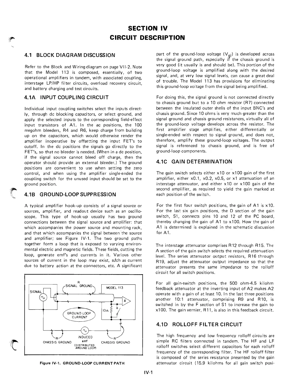
t 4.1B GROUND-LOOP SUPPRESSION
A typical amplifier
hook-up
consists
of
a signal source
or
sources, amplifier, and
readout
device such as an oscillo-
scope_ This
type
of
hook-up
usually has
two
ground
connections
between
the
signal source and amplifier:
that
which
accompanies
the
power
source
and
mounting
rack,
and
that
which accompanies
the
signal
between
·the source
and amplifier; see Figure IV-l.
The
two
ground
paths
together
form
a loop
that
is
exposed
to
varying environ-
mental electric and magnetic fields. These fields,
cutting
the
loop,
generate
emf's
and
currents
in
it. Various
other
sources
of
current
in
the
loop may exist,
sLlch
as
current
due
to
battery
action
at
the
connectors,
etc. A sign ificant
R
(SIGNAL
GROUND)
CHASSIS GROUND emf CHASSIS GROUND
(DISTRIBUTED
AROUND LOOP)
F~ureIV-l_
GROUN~LOOPCURRENTPATH
IV-l
part
of
the
ground-loop
voltage (V
I)
is
developed
across
the
signal
ground
path,
especially
i~
the
chassis
ground
is
very
good
(it usually
is
and
should
be). This
portion
of
the
ground-loop
voltage
is
amplified along with
the
desired
signal, and,
at
very low signal levels, can cause a
great
deal
of
trouble_
The
Model
113
has provisions
for
eliminating
this
ground-loop
voltage
from
the
signal being amplified_
For
doing this,
the
signal
ground
is
not
connected
directly
to
chassis ground
but
to
a
10
ohm
resistor (R7)
connected
betWeen
the
insulated
outer
shells
of
the
input
BNC's and
chassis
ground.
Since
10
ohms
is
very much
greater
than
the
signal
ground
and chassis
ground
resistances, virtually all
of
the
ground-loop
voltage develops across
the
resistor.
The
first amplifier stage amplifies,
either
differentially
or
single-ended with respect
to
signal
ground,
and
does
not,
therefore,
amplify these
ground-loop
voltages.
The
output
signal
is
referenced
to
chassis
ground,
and
is
free
of
ground-loop
components_
4.1C GAIN DETERMINATION
The
gain switch selects
either
xl0
or
xl00
gain
of
the
first
amplifier,
either
xO.l,
xO.2, xO.5,
or
xl
attenuation
of
an
interstage
attenuator,
and
either
xl
0
or
xl
00
gain
of
the
second amplifier, as required
to
yield
the
gain
marked
at
each position
of
the
switch.
For
the
first
four
switch positions,
the
gain
of
Al
is
xl0.
For
the
last six gain positions,
the
D
section
of
the
gain
switch,
Sl,
connects
pins
10
and
12
of
the
PC
board,
thereby
changing
the
gain
of
A 1
to
xl
00.
How
the
gain
of
A 1
is
determi ned
is
explained
in
the
schematic
discussion
for A
1.
The
interstage
attenuator
comprises
R12
through
-R15.
The-:
A section
of
the
gain switch selects
the
required
attenuation
level.
The
series
attenuator
output
resistors, R
16
through
R 19, adjust
the
attenuator
output
impedance
so
that
the
attenuator
presents
the
same
impedance
to
the
rolloff
circuit
for
all switch positions.
For
all
gain-switch positions,
the
500
ohm-4.5
kilohm
feedback
attenuator
at
the
inverting
input
of
A2
makes
A2
operate
with a gain
of
at
least 10. I n
the
last
three
positions
another
10: 1
attenuator,
comprising R9 and R 10,
is
switched
in
by
the
F section
of
Sl
to
increase
the
gain
to
xl00.
The
gain vern ier, R 11,
is
also
in
th
is
feedback
circuit_
4.10
ROLLOFF FILTER CIRCUIT
The high
frequency
and low
frequency
rolloff circuits are
simple RC filters
connected
in
tandem.
The
HF
and
LF
roll
off
switches select
different
capacitors for each rolloff
frequency
of
the
corresponding
filter.
The
H F rolloff filter
is
composed
of
the
series resistance
presented
by
the
gain
attenuator
circuit
(15.9 kilohms for
all
gain switch posi-
 Loading...