9|\||>|9|M;\g '|v/\Q|/\|33
33¢]-193 -1-|/\ a.|n5!=|
q|nq
wnnoe/\
e sapnpug
luawdgnba
pa1gnba1
aq_|_
'SS8OOJd
l.'l/\
8|dLU[S
e sg
J3/\OlJJ3.l-J8[I)|OS e
;o sueaw
Aq 1ap|os
6ug/\owag
ll
I
F -—
r,
_
.1L_
pt;
I
-
|
Q
-It-7-‘P?
u
--
f
' /
____
|
L#
(]0HJ.ElW
's/v\o||o;
qaea
;o UO!1d!.lOS8p
;agJq
V
--
_
's1|nse1
p006
a/\g6 sp01.|1au1
qlog '”>|0g/v\,,
e ;0 asn
amp, 1aq10
/
‘ ~»...§\
sq), pue 'J9AOlLl8J 1ap|os pa1e1ado
q|nq LUHHOQA
e 40 asn
sq), s|ge1ua
aug "pad e UJOJ].
J9p|OS aql
a/\0u.1a1 01 pasn
aq
"a;-___
uea
SpOL{l9LU
o/v\1 ;o auo
1aq1g3 "awn
a|qe1apgsu0o sa1gnba_1
|n;a1e0 Anegaadse aq ‘1uawa:)e|da1
10 uogloadsug
Jo; p1e0q
13,3
1_!nO.l!i)-p91U[Jd e LUOJ} pa/\ou1a1 we
S1U8UOdU.JOO
Aue
;|
‘
A|uea|:>
S1U8UOdL1JOD
a/\0wa1
oi "H0; sq],
aewep 01
10u
‘,0
§
&--—-—
E)NlHElCI'|OS
.Ll3HlO
(]El.LNlHd
8'9
'1ep|0s
40
aaJ;ee1e
1ug0[
aql Bug/\ea| ’>|:>!/v\ aql dn
/\|>|0gnb /v\0|; pue 1|aw ||g/v\
1u!0[
'P91l"5U°9
aq P|"°l-I5
'9J"P9°°Jd
luau‘
eql
ug1ep|os
aq1,\0
lsow
’spu00es M9}
e
u!L|1!/\/\
'pa1ap|osun
-U5!|V
9'41 '/\
U°!199S '51U9U°dW°9'W!11
19!}!ldW9
9111
4°
aq
01 1ug0[
aql
a/\oqe
/\|10eJgp
a1!/v\ papuens
aqn,
;0
9W051$n[P9
01
/9955999“ 9‘?! Alqeqold ll!/V\
1! 'P919ldW°°
9!
do1
uo U01! 5U!J9p|OS
loq 9 a0e|d
‘L-|/\ em6g:|
ug u/v\oqs
sv
$1U9U0dL1109
P9‘?!
J0 1U9W999|d91
PUB
5U!1°°LI59lqn°11
U9L|N\
'xn|,1 eseq-pgoe
'(J911!W9
ue asn saouelswnznga ou
Japun
:3_|_Q|\|
'1ugo[
8L|1
JGAO
9H1
01 l99d$9J
LI1!/V\ P91"$99W]' 9591|°/\ 95%|
9H1
UPLI1 559i
/v\0|;
01
xn|; aql ;0 awos Bu!/v\o||e ‘peuap osun
eq 01 1u!0[
5!1°1$!5U9J1
P9l9Jn195 9 J0 959140/\
1°199l|°9 9H1 19LI1
PL"? '/\
9L|1
40
dO1
uo
pgeuq
10 91!/v\
eql
aoe|d
uaq_|_ '><n|; 6ug1ap|os
9'0
/\lLl5"°1
5! (U°!19U"! 9P°!P 1°)
J°1'5!5U911
U°9!l!5
P999!q
889C]-Ll!SOJ
eql o1ug
pgeJq 6ugp|egqs
10
cu!/v\
pepueus
40
P19/‘M01949
9591|°/\
1911!ll-'9-01-95'?q
QLI1
lelll Jaqwalllal 01
saqaug Ma; e
dgq :sAAo||o;
se
peaawd '(1ue|e/xgnba
JO gg-917$
In-J99"
9!
1!
'5>I99Ll9
959l|0/\
5U!°P
9|!LllV\
"5U°!19U"!
J°199il°9
V|_|d"|V)
xn|;
6u!1ap|0s
aseq U!SOJ awos pue 'p!BJC]
papuens
PUP
eseq
8L|l
40 U0!1OB
epO!p
9L|1
5LI!>i09L|0
Aq J01S!$LIBJ1
peq
4Q Alddng Q ’(1u9||9QX3
5! pgqlgw
U! pgpugwwgggj lgql)
9 91BOO|
O1
a|qgssod
S8lil!l8LUOS S! 1!
'S)|O9L{O
8OU€lS[S9J
5Ll!Op
um! 5ug1ap|0s
p006 B sapnpu!
pa1gnbeJ
luauudgnbg 'poq1eu1
U9L{/\A
'8|qn0J1
eql 1u!0du!d
/\||BO!,l!09dS
ueql
UBO $>|0€-M10
sgql
Aq pa/\agq0e aq ueo >|1o/v\ ueap A||eu0g1de:>x3
‘pad
9L|1
99UB15!$9J
PUB
95Bl|0/\
’1!n9J!0
PBOIJI-J/\0
8L|1
01 JO $85918
uu0J;1ap|os ua1|0w
aql dn
/v\e1p 01 >|:>g/v\ e se pgwq
6ugp|e!qs
J9!}!|dLUB
9L|1 40 BUO O1
e|qno11
Bql 819|0S!
S>|09L|0 |9u5!$
10
a1!/v\ pepue11s;0 q16ua| e sasn
qagq/v\ poqlew
2 sg 6ug>|ogN\
181}V 'S|Bu5!S
lndul
1Su!B6e
s|eu6gS
1nd1H0
5u!J9dw00 /\q
pa>|oeqo
aq Aew saels
.l9[}!|C|LUE?
0*/v\1 aql ‘sa6e1|0/\
A|dclns
z# qQ|_|_|_3W
.l9N\Od
aql 6ug>|oeq0
.l9l}V 'a|qnoJ1
aql 6ug1e|osg
10; uoglew
-J0;u!
1uag:)!;;ns
Sp!/\O.ld p|noqs '(||/\
uogloag)
soglewaqos
.S9|OL|
pue
suuwegp
1noAe|
a'q1 qlg/v\
1aq1a601 'UO[ld[J3S8(]
lgnzugg
aql
mum;
.l8p|OS ||é
Jeep
/\|a1a|duuo0
01
JGAOLUSJ
J8p|OS W1
I/\| “Q9393 'sw°1d‘“’\5
mil 5u!u!‘*“919p
U! |n¥d|9L| aq
am asn
Ipamwal uaaq seq luauodwoo
am JGHV
.pJeOq
||g/v\
'|| UO!1Q8S'S>|O3L|Q
|eg1gu|
ug ua/\g6
e1npa:>oJd
pue dn-1as
a\.|1 mum;
sea; sg luauodwoo
aql
|!1un
speag
ea1,Lun
aql
9L|i'p91S91 pug
pamauuoa Auadold S!
J9!=‘!|dwB am “WM
40
qsea 10;sgq1
5U!1B9d9J
/\|a/xgssaoons
pue
‘a|qgss0d se Je; se
SWQWW/\$
9H1
U!B1J99SB
pue
'9|C|O.l1
aq1
5,0
sasneo
|eu1a1xa
aloq am
qnoml peel am ‘Ind
O1 luauodwoa em Huppojn
Aue
au!uua1ap
01 A11 'SS9OOJd
6ug100qse|qn0J1
aql paads o_|_
pue spea|
aql 40
auo
01
leaq
ug/\|dde
Aq
pa/\0wa1
eq
ueo luauoduuoo
aql ‘sa|oq
aql
ug spea| aql
;0
||e em;
3UnC|3QOHC|
2'9
01 a|qgssod
1ou
sg1g;g
5/\|snoeue1|nLugs
sa|0q
aql ug
am; spv2a|
s1! ;0
||e
a/xeq
1SI'1LLl awgl
e 1e auo
PGAOLUBJ
aq 10uue:> qogq/v\
Vuueuem aw’
a1Bp!|e'\u! pmoa Os
Speal LIMA luauodwoo
V _9|Oq am mo“
peel am Bumnd
op 01 am|ge;se‘1gede1
p|a!; e Bugldwane
01 JO‘_\.lC|
paloeluoo
a|gL|/v\
leeq
A|dde
01
anu!1u0o
‘am;
-lou
sg pee|
aql
;|
'SJ8[|d
sq 9A!]'e1uaSeJd9J
@0139} paZ!JOL|1ne
ue leql luelmdw!
asou-6u0|
a|qe1gns
ugsn
‘pmoq
aql
,10
apgs luauodwoo
/Welnagljed
S! 1! A-LNVHHVM
U! “us S! luewmlsu!
am won eloq am qnojul
peel am ‘Ind ,pa/mwaj
8L|1 ,1! eseo Aux?
u|
ugedeu
JO}
M0102;
aql 01 1; 6ugum1a1
1ap|os
eql 1a1;V
'/Uessaaeu
ueql 1a6u0|
Aue
1eaq 01
10u ems O1
pasoddo Se Haswm
luawmlsu! aw’ Bumedaj
JO swam
e>|e_|_
'a|oq pue
ped sq),
LUOJ} 1ap|0s
sq),
8/\OLL|9J 01
J9/\OLU9.l 9A!]'e'aJ aw’
U0 a3!Ape JO} uonejodjoa
“M98895 pauddv
Jeplos am
asn ,SMOH
_1uauOdwOO
uolaoupd
19e1u0:>
p|noqs JGSH
aq1 5u!10oqse|qn0J1
Aue
eql allsoddo
ems aql ped
5U!lC|lU811B
9JO}9C]
JO 1U8UOdllJOO JO
l!I'\OJ!O O!].!O8C|S B O1
paeomd
‘luauodwoa
e a/\0wa1
O_|_
'1uauodw0o
HLI1
allsoddo
pelmos!
S!
walqojddaql
8?/:0
-lmdlau 9/(2 “W25 uonoas
SM1 U!
ems am
U0 ped am won pamwaj
aq lsmu Japlos
aql _(d!1 pau!|1no
sampaom 8L|1. JBSSBOSU
aq
ew u!100qsa|qno11
SNVLM
ad/Q WM OZLOVSGHVL
ad/£1 TIVM)
J3/mod |euo!se:)00‘1uawnJ1suga|qeg|aJ
e sg 311
|ap0|/\| aqn, q6n0q1|v
-po1.u,10
um! 6ug1ap|os
p006
e pue
(papuewwoam
(_'1‘08L#
:|;|()-H3Q|"|()S
ad/£1
av-§)|\|(])
.l9l\OUJ9J
1ap|0s
pa1e1ad0 N()|J.QC|0H.].N| L 9
9Nl.l.OOHS3'l8OH.l.
lI\
NOILOHS
32
Q
D
‘\\
J
(
SECTION
VI
TROUBLESHOOTING
6.1
INTRODUCTION
Although
the
Model
113
is
a reliable
instrument,
occasional
troubleshooting
may
be
necessary;
the
procedures
outlined
in
this
section
will be helpful.
Once
the
problem
is
isolated
to
a specific
circuit
or
component,
or
before
attempting
any
troubleshooting,
the
user
should
contact
Princeton
Appl ied Research
Corporation
for
advice
on
the
relative
merits
of
repairing
the
instrument
himself, as
opposed
to
returning
it
to
the
factory
for
repair.
In
any
case, if
the
instrument
is
still in
WARRANTY,
it
is
particularly
important
that
an
authorized
factory
representative be
contacted
prior
to
attempting
a field repair,
as
failure
to
do
so
could
inval
idate
the
Warranty.
6.2 PROCEDURE
To
speed
the
troubleshooting
process,
try
to
determine
any
external
causes
of
the
trouble,
and ascertain
the
symptoms
when
the
amplifier
is
properly
connected
and
tested.
The
set-up
and
procedure
given
in
Initial Checks,
Section
II, will
be helpful in
determining
the
symptoms.
Section
IV,
the
Circuit
Description,
together
with
th.e
layout
diagrams and
schematics
(Section
VII),
should
provide
sufficient
infor-
mation
for
isolating
the
trouble.
After
checking
the
power
supply
Voltages,
the
two
ampl ifier stages
may
be
checked
by
comparing
output
signals against
input
signals.
After
signal
checks
isolate
the
trouble
to
one
of
the
amplifier
stages
or
to
the
overload
circuit,
voltage
and
resistance
checks
can
then
specifically
pinpoint
the
trouble.
When
doing
resistance
checks,
it
is
sometimes
possible
to
locate
a
bad
transistor
by
checking
the
diode
action
of
the
base and
collector
junctions.
Wh
ile
doing
voltage
checks,
it
is
usefu I
to
remember
that
the
base-to-emitter
voltage
of
a
forward
biased silicon
transistor
(or
diode
junction)
is
roughly
0.6
V,
and
that
the
collector
voltage
of
a
saturated
transistor
is
less
than
the
base voltage
(measured
with
respect
to
the
emitter).
When
troubleshooting
and
replacement
of
bad
components
is
completed,
it will
probably
be necessary
to
adjust
some
of
the
amplifier
trim-components.
Section
V,
the
Align-
ment
Procedure,
should
be
consulted.
6.3 PRINTED CIRCUIT SOLDERING
If
any
components
are removed
from
a
printed-circuit
board
for
inspection
or
replacement,
be especially careful
not
to
damage
the
foil.
To
remove
components
cleanly
requires
considerable
care_
Either
one
of
two
methods
can
be used
to
remove
the
solder
from
a pad.
One
entails
the
use
of
a
vacuum
bulb
operated
solder
remover,
and
the
other
the
use
of
a
"wick".
Both
methods
give
good
results.
A brief
description
of
each
follows.
METHOD
#1
Removing
solder
by
means
of
a
solder-remover
is
a simple
process.
The
required
equipment
includes a
vacuum
bulb
VI-'
operated
solder
remover
(UNGAR
type
SOLDER-OFF
#7805
recommended)
and
a
good
soldering
iron
of
mod-
erate
power
(WALL
type
14HDG40120
with
type
W14KS
tip).
The
solder
must
be removed
from
the
pad
on
the
side
opposite
the
component.
To
remove a
component,
proceed
as
follows:
Heat
the
pad
on
the
side
opposite
the
component.
As
soon
as
the
solder
flows, use
the
solder
remover
to
remove
the
solder
from
the
pad
and
hole.
Take
care
not
to
heat
any
longer
than
necessary.
After
the
solder
has
been
removed, pull
the
lead
through
the
hole
from
the
component
side
of
the
board,
using
suitable
long-nose
pliers. If
the
lead
is
not
free,
continue
to
apply
heat
while
pulling
the
lead
from
the
hole.
A
component
with
leads
which
cannot
be removed
one
at
a
time
must
have all
of
its
leads free in
the
holes
simultaneously;
if it
is
not
possible
to
free
all
of
the
leads in
the
holes,
the
component
can be
removed
by
apply ing
heat
to
one
of
the
leads and
"rocking"
the
component
to
pull
the
lead
through
the
hole
as
far as possible,
and
successively
repeating
this
for
each
of
the
unfree
leads until
the
component
is
free
from
the
board.
After
the
component
has been
removed,
use
the
solder
remover
to
completely
clear
all
solder
from
the
holes.
METHOD
#2
Wicking
is
a
method
which
uses a length
of
stranded
wire
or
shielding braid
as
a
wick
to
draw
up
the
molten
solder
from
the
pad.
Exceptionally
clean
work
can
be achieved by
this
method.
Equipment
required
includes a
good
soldering
iron
(that
recommended
in
Method
#1
is
excellent),
a
supply
of
stranded
braid,
and
some
rosin base
soldering
flux
(ALPHA
346-35
or
equivalent). Proceed
as
follows: Dip a few
inches
of
stranded
wire
or
shielding braid
into
the
rosin-base
soldering flux.
Then
place
the
wire
or
braid
on
top
of
the
joint
to
be
unsoldered,
allowing
some
of
the
flux
to
flow
over
the
joint.
NOTE:
Under
no
circumstances
use an
acid-base flux.
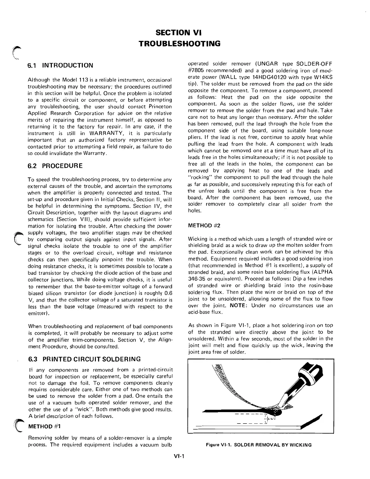
As
shown
in
Figure
VI-l,
place a
hot
soldering
iron
on
top
of
the
stranded
wire
directly
above
the
joint
to
be
unsoldered.
Within
a
few
seconds,
most
of
the
solder
in
the
joint
will
melt
and
flow
quickly
up
the
wick,
leaving
the
joi
nt
area free
of
solder.
-===================~/
Figure
VI-l.
SOLDER
REMOVAL
BY
WICKING
 Loading...