I
1
I
To do zero adjustment,
place
both coupling
switches
in
the
ground
position,
set
the L.F.
Rolloff switch
to DC,
+80
.
-
and
set
the gain
switch
to the position
to be used.
Then
~
adjust
the
front-panel
zero potentiometer
for 0 V
at the
+10
i iii"
'*°
output.
l
ix
|
+60
i
V i i
'30
3.9
DC
ZERQ ADJUSTMENT
l
I
..
i 1/
l.O
O6
F Eout
O
I O
+20
l as 1
l i
-70
TOTAL
GAIN
=
GAIN x
Fgq
x
}-Ee°i'-i
Ell‘!
Lp
Ell’! Hp
+|Q
ML.-. i
.1
.
-80
||l
|i
:1
il
ll
2
I
Ind
-I
'4I
AII
I—
)
LEAD
+
OI
o
J__
via
oo
EESLAG
oscnezs
+
3!
Q
E
oscn
+30
1
2-
~ . ,4
» 1-»
-T »
~60
ii I
.
l
.1
__
.
Q
.
l.
. ,l_l
i
-90
Ol
.lO
l.O
l0.0
IO0.0
IIIIIIIIIIIIIIIIIII
f
f
T
-- 0.
--
IIIIIll||IIIIln||
f me Mme
L
'
(READ
LEFT
DEGREE
SCALE)
(READ
RIGHT DEGREE
SCALE)
0,3
i_--'"|i1—---in
tom.
Pans:
= ALGEBRAIC
suu
or
HF
a
LF PHASE
ANGLES
lllllii
_
\-
' -1
-
-
‘s
II
II
SDcF"FF“liF||||lm|
IIIII
I
I
ll
__ll
6
‘HF
sue
LIIIII
||III'nn|
_--
_---II
_I---I
IIIIII
.llII
_--I
__—-
iiii
--I
II-I
IIII
_-
I
I
i
V
I1|
|ll
III
III
:::
_-II
iiii
||||
llII
IIII
::::
-III
——II
l0.0
L.__i____________
____.
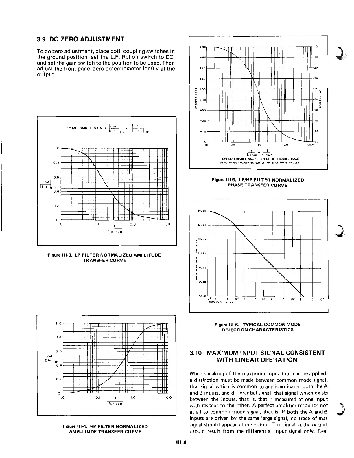
Figure Ill-3. LP FILTER
NORMALIZED
AMPLITUDE
"TRANSFER CURVE
i i
Figure
Ill-5.
LP/HP FILTER
NORMALIZED
PHASE
TRANSFER
CURVE
.._.........
"-—-——_————-1
--It
T '
—IIIIl—II_II§l!—II-IIIII
I40
as
.
.
._ _
-IIIII_---IIII|._---IIIII
» ,
_IIIIl:-I_IIIIlilI_IIIII
_IIIIl——I_IIIIl—I§:!lIIl
I00
l3OdB _
I20
dB
NdB
" lOdB
REJECTON
O68»
_
commonMODE
w6
O68
aoaai
- ~
-
:01
2 5
io‘ 2
5 io‘
2 5
io° 2
5 io°
FREQUENCY
IN Hz
S
III
ll
-11-IIIIl—IZ-III
I
_-I_IIIII__'l_III
I
Illl I I I
E!!!!::::2:4!!:‘
_—--IIIIl'I—--
IIIIII_II!=l
I-IESIII -
_ I-IIIIl_-
. O.
I
ill
N
*III
III
IIII
IIIII
IIIIII
-EIEEIEIB
Oll|l‘ll'
IIIIIIII
IIIIII
IIIII
IIII
ll|l|IIIIl|l|iIII::'-all
—‘
Figure Ill-6.
TYPICAL
COMMON
MODE
n|||IIIInuiIw.--nun
Illl||IIIIIll||I'IIIl|l||
REJECTI
ON
CHAR
ACTE
R ISTICS
I-=iiIiIII===iIiIl—.‘-iiiiii:
°~8 IIIIIIIIIIIIIIIIMIIIIIIun
'
IIIInu||IIIIIln|rII-Innu
IIIIIIIIIIIIIIIIIIIIIIll|||
IIIIn|||IIIIIllnII-cum
O 6 IIIIIIIIIIIIIIIIIIIIIIlln
i
i II=::::::II=:'§::i--'
E 9”’ IIIIIll||IIII,:|l
E in Hp
IIIIl||||IIIIAll
0,, IIIIIIIIIIIIIAIII
gggg
3.10
MAXIMUM
INPUT SIGNAL
CONSISTENT
::::
WITH
LINEAR
OPERATION
nu
IIII
iii!
-
- -
-
nu
When
speaking
of the maximum
input
that
can
be applied,
a
distinction
must be
made between
common
mode signal,
:::
that
signal
which
is
common
to and
identical
at both
the
A
"'
and
B
inputs, and
differential
signal,
that
signal
which
exists
'°°
between
the
in
ut th
t ' th t'
m
ed t
n 'n
ut
T__'
'-
ps,
ais,ais
easur
aoeip
U3“
with
respect
to the
other.
A
perfect
amplifier
responds
not
at
all to common
mode
signal, that is,
if
both
the
A
and
B
inputs
are
driven by
the
same
large
signal,
no trace
of
that
Figure |||_4_
HP HL-I-ER
NQRMAUZED
signal should appear
at the
output. The
signal
at the
output
AMPLITUDE
TRANSFER
cunvE
should
result
from
the
differential input signal
only.
Real
Ill-4
;
l
3.9
DC
ZERO ADJUSTMENT
To
do
zero adjustment, place both coupling switches in
the ground position, set the L.F. Rolloff
switch
to
DC,
and set the gain
switch
to
the
position
to
be
used. Then
adj ust the front-panel zero
potentiometer
for 0 V at the
output.
TOTAL
GAIN
0.6
~
~LP
0.4
f:=--
0.2
o
0.1
GAIN
x
jEout
I x
~
E
,n
L P
[E;;;I
HP
1.0
10.0
figure
111-3.
LP
FILTER
NORMALIZED
AMPLITUDE
TRANSFER
CURVE
0.8
0.6
I
~
E in
IHP
0.4
0.2
o
.01
0.1 1.0
Figure
111-4.
HP
FILTER
NORMALIZED
AMPLITUDE
TRANSFER
CURVE
100
10.0
111-4
140
dB
130
dB
120 dB
IIOdB
IOOdS
90dB
80
dB
..i.."
_f
f
L
F3dB
fHF3dB
(READ
LEFT
DEGREE
SCALE)
(READ
RIGHT
DEGREE
SCALE)
TOTAL
PHASE
= 4LGEBRA'C
StM
CF
HF
6 LF
PHASE
ANGLES
Figure
111-5.
LP/HP
FILTER
NORMALIZED
PHASE
TRANSFER
CURVE
......
'"
"
c-
-
-
"\t-,.
"\
r\.
~
.-
r--
..
-
-
~
r\.
I--
-
[1]
"
'-;-
.
'0
2
10
10'
2
10
FREQUENCY
IN
H l
Figure
111-6.
TYPICAL
COMMON
MODE
REJECTION
CHARACTERISTICS
3.10
MAXIMUM
INPUT
SIGNAL
CONSISTENT
WITH LINEAR OPERATION
When speaking
of
the
maximum
input
that
can
be
applied,
a
distinction
must
be
made
between
common
mode
signal,
that
signal which
is
common
to
and
identical
at
both
the
A
and B inputs, and differential signal,
that
signal
which
exists
between
the
inputs,
that
is,
that
is
measured
at
one
input
with respect
to
the
other.
A
perfect
amplifier responds
not
at
all
to
common
mode
signal,
that
is, if
both
the
A and B
inputs
are driven by
the
same large signal,
no
trace
of
that
signal should appear
at
the
output.
The
signal
at
the
output
should result from
the
differential
input
signal
only.
Real
)