€'l|l
'pUO.l5
sgsseqa
01 pun016
|eu6gs
aql
Buguoqs a6e1|0/\ 1nd1n0‘u0g1gs0d
Qq
aql
ug 1;a|
sg 1! ;| 'uo!1!sod
3(]
pgo/\e
'UO!139[8.l
doo|-pun015
LU|’1UJ!XBLU
105
'1o1sgse1 wqo
sq),
ug1;a|
aq 1ou
p|n0qs
qalg/v\s
:|:|Q"|‘|()H
:|-| aql 'u0g1gsod
Q[_ e L|5OJL|1
pun016
sgsseqa
01 pamauuoo
aw (A||euJe1ug 5U!|dOQ QV aql
01
19s
sue seqolg/v\s
6u!|dnoQ
L|1oq 10 euo ;|
J9l.|18501
pagl)
SPUHOJ6
|eu6gs
0/v\1 sq),
1eq1 JGQUJGUJSH
'S()[1S!.l81OB.lEL|O
1e,LsueJ1
aseqd
pue apn1g|du.|e
[I)9Z[|BLU.lOU
am
samg;
Bug/v\o||o; aq_|_
'(dn>|0gd
z|_|
Q9 JO
‘Aauanbeu;
's1ndug 9 pue
V sq),
1e sa6e1|0/\ aL|1;0
a:)ua1a;;gp
aql
qgq
’:>p
se
qons) s|eu6gs
palue/v\un
81QU[LU[|9
01 pasn
aq ueo
setup, uge
aql 01|enba sg
a6e1|o/\
1ncl1n0
aqi
'81B!Jd0JddB
se
s1a1|g;aq1
'u0g1gppe
u| 'asg0u
|BLlJ.|9L{1 aamos
eql sazgwgugw
‘ae ug
.I9L|lO 9L|l pue
0p ug euo
10
suoglgsod
op
10 ae Lnp!/v\pueq
eql Bugzgwgugw
'S0[1S[.l91OBJQL|I)
ssedpueq
8p[AO.ld
ug
saqcng/v\s
6u!|dnoo
qloq
aoe|d 'u0g1e1ado
|e!1ua1a;;!p
.IO:|
01 p91B.IOd.lOOU!
we s1a1|g;
ssed-qgq
pue
ssed-/v\o|
sagas
‘pa-ugsap
se 5ug|dn0o
op JO oe
01 qolg/v\s
1ndu!-|eu6gs
SH3_|_-|
H
Ssvd-H9||_|/Ssvd-M0-|
[8
sq),
a:>e|d pue
‘uoglgsod puno16
sq],
01 qolg/v\s
5u!|dnoo
lndug
pasnun
8L|1
a:>e|d A|dwgs
'UO!18.l8dO
papua-a|6ugs
105
'papua
'A|a1egpawuug
pawnsw
-a|5u!s
10 A||eg1ua1a;,;!p pa1e1ado
aq
Aew Jeg;g|du.1e
aq_|_
aq ueo
uoglmado
|ew1ou
1e\.|1
os suolgaedea
sq),
;0 amqosgp
&
1se;
sasneo
a|66o1
Ma/\o0e,|
peope/\0
pepeo|6ug1ds
aql
NO|_|_vH3dO
ugsseud
‘(Z-|||
amgd
‘elep amp, Ma/\o:>eJ
sq),
aas)
85.lBL{0
..|Vu_N3H3:H'0/G3GN3_3_|9N|S
8-8
-sgp
S.lO1!OBClBO
1a1|g,1
pue
6ug|dn0:>
|g1un
pa|qes!p
u!eu1a1
pue
a1em1es
||g/v\
Jagudwe
aql
‘(| uoglaeg)
suogleoggoads
megs
aql ug paleogpug
|a/\e|
aql spaeoxa
|eu5gs
lndug aql ;|
||n;
paaoxa p|no:>
1as;;o aql 'suge6
qgq 1V unooo Aew (xew
Vd
QQL)
luauno
1as;;o lndug
aql
mm; 6ug1|nsa1
s1as;;0
AH3/\QQE|H
.LSV:|
C|VQ'|HE|/\Q
9'8
:l:|O1'|CH
AQN3U3H:|
M01
S/\
3W|.|.
AH3/\OQ3U
_|VQ|dA.|.
'Z'||| 9m5!:|
(ZH)
9N|li3$
:!:!O-‘I108
XQNQHQQHJ
MDT
ow
2'0
|'o
20'
no
7
41
I
k
w
'
"
9
XIX
-OIX
NW9
Q
A83/\OO3H
/\ Q3; = 6ug|dno:>
op
2H
Q9
‘/\
gm
=
6u!|dno:>
oe
:(apow
uowwoo
JO |e!1ua
—J8}}!p)
a6e1|0/\
1ndu|
wnwgxew
a1n|osqv
‘Q
3W.L
'S8pOLU
||e ug
Ma/\ooa1
"
8lB!p8LULU! sap!/\o1d
uonnqqsnd "|/\Q aq_|_
'0p
1e
las
qolg/v\s ;;0||03
Aouanba1,_|
N 0| X
_ X2 X
Nlvg
MO"| aql pue :>p sg 6ug|dnoo lndug
aql
~
uaq/v\ a|qe|ge/\e
sg
au.|g_L
A19/\o:>aH
wnwgugw
(1)38)
'(spuooas Q1, = 33) pappe sg JOlS!S8.l “
’ Oz
wqoauu QQL e |.p,g/v\ S8!J8S_U! JOl!O8dBO
gr!
yo
e 'UO!1!SOd
6ug|dno:>
oe
aql
u|
'u0!1gsod
op 8L|1 ug
qzng/vxs 6ug|dn0o lndug am, L|1!N\ ua>|e1 eleq
'.|ag;g|duue 1s1g;
aqa, ;o 85818 1nd1no
*
" 92
eul
elmnles
01
lndug luagoggns
= pl-2O|J8AQ
'an|e/\ a1e1s
Apeals
40
1|o/\
|,
ugqlg/v\ 01
a|11as
01 1nd1,no
aql
J0;
pa1gnba.|
8LU!l = au.1g_|_
Ma/\0oaa
.?
-—O€
I I
A
P
4
+
30.-------------,--------------,-------------,---------------
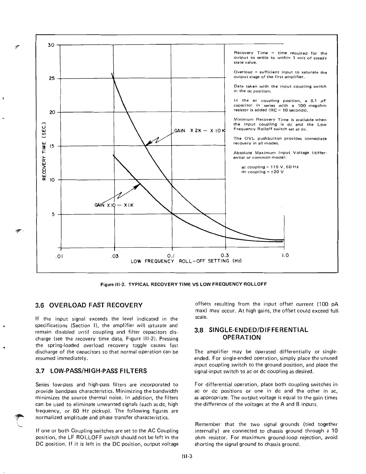
Recovery
Time
=
time
required
for
the
output
to
settle
to
within
1
volt
of
steady
state
value.
25~--------------~--------------_r--------------~
Overload
~
sufficient
input
to
saturate
the
output
stage
of
the
first
amplifier.
20
-:
(.)
Data
taken
with
the
input
coupling
switch
in
the
dc
position.
In
the
ac
coupling
position,
a
0.1
J.lF
capacitor
in'
series
with
a
100
megohm
resistor
is
added
(RC
~
10
seconds).
ILl
(/)
GAIN
X 2K - X
10
Minimum
Recovery
Time
is
available
when
the
input
coupling
is
dc
and
the
Low
Frequency
Rolloff
switch
set
at
dc.
ILl
15
::f
t=
>-
a::
ILl
>
8
ILl
a::
10
5
The
OV
L
pushbutton
provides
immediate
recovery
in
all
modes.
Absolute
Maximum
I
nput
Voltage
(differ·
ential
or
common
mode):
ac
coupling
~
115
V,
60
Hz
dc
coupling
~
±20
V
.01
.03
0.1
0.3
1.0
LOW
FREQUENCY
ROLL-OFF
SETTING
(Hz)
Figure
111-2.
TYPICAL
RECOVERY
TIME
VS LOW FREQUENCY
ROLLOFF
3.6 OVERLOAD FAST RECOVERY
If
the
input
signal
exceeds
the
level
indicated
in
the
specifications
(Section
I).
the
amplifier
will
saturate
and
remain
disabled
until
coupling
and
filter
capacitors
dis·
charge
(see
the
recovery
time
data,
Figure
111-2).
Pressing
the
spring·loaded
overload
recovery
toggle causes fast
discharge
of
the
capacitors
so
that
normal
operation
can
be
resumed
immediately.
3.7 LOW-PASS/HIGH-PASS FILTERS
Series
low·pass
and
high·pass filters are
incorporated
to
provide
bandpass
characteristics.
Minimizing
the
bandwidth
minimizes
the
source
thermal
noise. In
addition,
the
filters
can
be
used
to
eliminate
unwanted
signals (such as
dc,
high
frequency,
or
60 Hz
pickup).
The
following figures are
normalized
amplitude
and phase
transfer
characteristics.
If
one
or
both
Coupling
switches
are
set
to
the
AC
Coupling
position,
the
LF
ROLLOFF
switch
should
not
be
left
in
the
DC p.osition. If
it
is
left
in
the
DC
position,
output
voltage
111-3
offsets
resulting
from
the
input
offset
current
(100
pA
max)
may
occur.
At
high gains,
the
offset
could
exceed
full
scale.
3.8 SINGLE-ENDED/DIFFERENTIAL
OPERATION
The
amplifier
may
be
operated
differentially
or
single·
ended.
For
single·ended
operation,
simply
place
the
unused
input
coupling
switch
to
the
ground
position,
and
place
the
signal·input
switch
to
ac
or
de
coupling
as
desired.
For
differential
operation,
place
both
coupling
switches
in
ac
or
dc
positions
or
one
in
dc
and
the
other
in ac,
as
appropriate.
The
output
voltage
is
equal
to
the
gain
times
the
difference
of
the
voltages
at
the
A and B
inputs.
Remember
that
the
two
signal
grounds
(tied
together
internally)
are
connected
to
chassis
ground
through
a 10
ohm
resistor.
For
maximum
ground-loop
rejection,
avoid
shorting
the
signal
ground
to
chassis
ground.
 Loading...