3_13
USING
A
SIGNAL
INPUT
Figure
lll-9A
is a family
of amplitude
transfer
curves
TRANSFQRMER
for
a
typical
Model
AM-1
wired
for
a 1:100
turns
ratio,
and Figure
lll-9B
is the corresponding
family
of
HOW
a Signa|
input
transformer
can
improve
|OW_nOise
noise
figure
contours.
In
the transformer-amplifier
performance
was
discussed
in
Subsection
3.2.
There
it was
system’
the
noise
ngure
ootenneo
_nonn
n|'9B
ore"
indicated
that
a
transformer
often
has
a bandwidth
narrow
demmetesl
ad.
Therefore,
this
noise -figure
can
be
compared
with
the
amplifier
it
is being
used
with,
and
that
regarded
as
tne
system
overen
no'se
n9ure'
HoWe_Ver'
the transformer
adds
its
own
noise
to
the total
noise.
For
the
nansformee
frequency
response
and
tne
amonner
this reason,
it
is
best
to have
noise
figure
contours
and
response
set
Yvnn
tne
ronon
eontro's
must
be
eom'
amplitude
transfer
curves
for
the
transformer.
Princeton
o'neo
to
ootem
tne
system
overen
response
enereeter'
_
I
Applied
Research
Corporation
manufactures
three
mag
'st'es'
netically
shielded
signal
transformers
that
may
be used
with
the Model
113:
the
Models
AM-1,
AM-2,
and
190.
Data for
each
of these
transformers
follows.
§lso
,,‘,§‘,
283222
_-_
_
"
42
IOOQ
SOURCE
— **
(1)
Model
AM-1
3.1,.
.
_l-
\
Z so
_L
\
A
general-purpose
frequency
response
and
changeable
F
turns
ratio
render
the AM-1
the
most
versatile
of
the
three
transformers.
NOTE:
The
outer
connector,
as
the
transformer
comes
from
the factor
is wired
for
a
/
\
'
IO
2
5
IOe
2
5
IO3
2
5
IO‘
Z
I
Eour/EuTUR
3 5000
SOURCE
' ' '' '
' "
‘I’
m
R
§
-DLIQQQ
ooooo
\
\
\-
\
I‘.
I
/
,'"’
\\
\
.w»~..
\
l
differential
output
with
separate
ground
return
(see
F"E°“E"°*
Figure
Ill-8A).
When
using
the
transformer
with
the
Model
113,
one
half
of
the
secondary
will
be
shorted
Figure
|||-9A_
FREQUENCY
RESPQNSE
QF
TYP|CA|_
to ground,
if
the
Model
113
is
operated
single-ended
as
MODEL
AM-1
TRANSFORMER
recommended
in
Subsection
3.3,
unless
the
output
connector
is
rewired.
To use
the
full
1:100
turns
ratio
I
From
Figure
lll-9B,
for
a
turns ratio
of 1:100,
the
rtne
Center
tap
W're
must
be
removed
from
p'n
I
optimum
source
resistance
is
between
10
and
100
(ground),
and
the wire
going
to
pin 3
removed
from
ohms.
If
a
source
resistance
in
another range
is
to be
pi"
3 and
reeenneeted
to
pl"
1'
as shew"
In
Figure
used,
the
operator
may
consider
changing
the
turns
I“'8B-
ratio
to
shift
the lowest
noise-figure
resistance
range
to
that
being
used.
The source
resistance
scale of Figure
lll-9B
should
be
multiplied
by
the
factor
104N2,
mm
ourrur
mm
moo
outrur
where
N
is
the
step-up
turns
ratio
being used.
||:
g
Required
wiring
and
scaling
information
is given
in
1-
-Q»
‘I
Figure
Ill-10.
SCI-IEMATIC
OF UNMOOIFIED
SCHENATIC
OF
MODIFIED
AM—I
AM-1
INPUT
OUTPUT mnur
OUTPU1’
ll
ILAC
'
A0!
,
nucx
1
$
a
%
0:
'/~
'/~
(I ...
‘\
\\
ll
0 c>m!,>
0
ea
‘¢?
etli’
o
o‘:,)
r
MAC!
A¢|(
r
c><3 0
ca
o 0
l
ACK
0
ILACK 0
0
r no
‘r 1°
‘mm
~
-
‘do
sumo
smuo
INTERNAL
COM£CT
IONS
INTERNAL
CONKCT
IONS
OF
OF
|O-I
.
.
I5dB
LMMODIFIED
AM_I
MODIFIED
AM-1
A
B
290K
0-
\
O
SHIELD
SNIIID
SHIELD
SNIHD
/ \/~
I
lonmsSTANCE
SOURCERES
5O
O
~;_;.;.¢..§f§:§§§§5i§§§§55§55;Z~E?’fifffjffeiIf_ifififffifijfffjfj;
3d B
check
“frequency
response
curves
above
before
operating
in shoded‘f§§§§§§;'§§§§§i
2
355557.-;§;1;§:~;§;§.
‘e9
'9":
I O
;-;~;-
.;I~.'.~11-QC-5'1’."L1-L».-J-I~'T'I-.-j~;»j-;.;.;.v.~I\fl'L~L-L53'§'I~Z£-Z~i~;-'1'I'I~I-l-I-Ti-lg‘.~;;~;-I~‘l'I-.-L-l-1-I-'-"I-I.>L-Li-J-’-'I'I>I-1I~;»l»iTI'l_
OO
'2
we 1
/
RATQ
O
TURNS
ads-ii
-'|
l
5_dBl
lOdB"'r“"*'-——'
1
r
l0
I02
|o3
lo“
FREQUENCY
(Hz)
Figure
Ill-8.
MODIFYING
THE
AM-1
TRANSFORMER
Figure
III-9B.
NOISE
FIGURE
CONTOURS
FOR
FOR
USE
WITH
THE
MODEL
113
PREAMPLIFIER
TYPICAL
MODEL
AM-1
TRANSFORMER
6
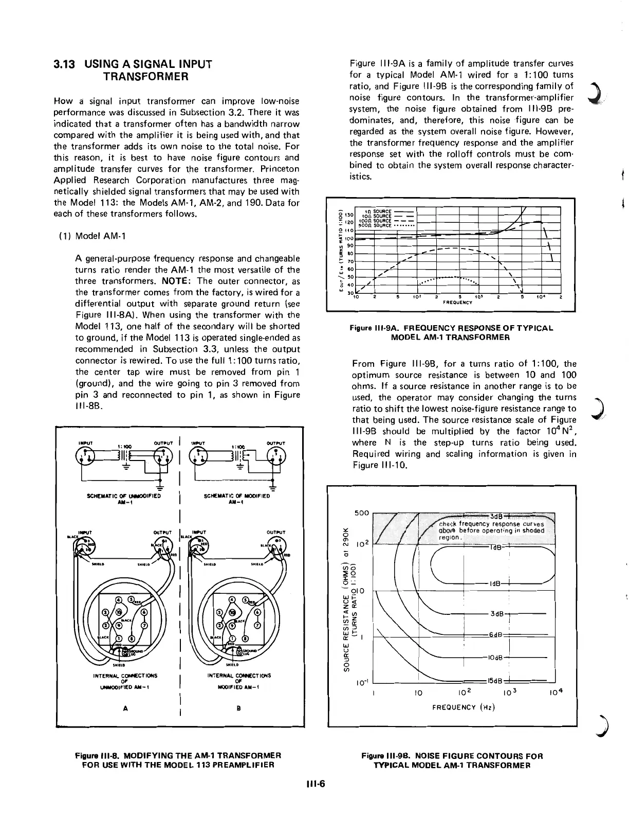
3.13 USING A SIGNAL INPUT
TRANSFORMER
How a signal
input
transformer
can improve low-noise
performance
was discussed
in
Subsection
3_2_
There it was
indicated
that
a
transformer
often
has a
bandwidth
narrow
compared
with
the
amplifier it
is
being used
with,
and
that
the
transformer
adds its
own
noise
to
the
total noise.
For
this
reason,
it
is
best
to
have noise figure
contours
and
amplitude
transfer
curves
for
the
transformer.
Princeton
Applied
Research
Corporation
manufactu
res
three
mag-
netically shielded signal
transformers
that
may be used
with
the
Model 113:
the
Models AM-1, AM-2, and 190. Data
for
each
of
these
transformers
follows.
(1) Model
AM-1
A general-purpose
frequency
response and changeable
turns
ratio
render
the
AM-1
the
most
versatile
of
the
three
transformers.
NOTE:
The
outer
connector,
as
the
transformer
comes
from
the
factory,
is
wired
for
a
differential
output
with
separate
ground
return
(see
Figure 11I-8A). When using
the
transformer
with
the
Model
113,
one
half
of
the
secondary
will be
shorted
to
ground,
if
the
Model
113
is
operated
single-ended as
recommended
in
Subsection
3.3,
unless
the
output
connector
is
rewired.
To
use
the
full 1:
100
turns
ratio,
the
center
tap
wire
must
be
removed from pin 1
(ground),
and
the
wire going
to
pin 3 removed
from
pin 3 and
reconnected
to
pin 1, as
shown
in
Figure
111-8B.
SCHEMATIC
OF
UNMODIFIED
AM-'
I
NTERNAL
CONNECTIONS
OF
UNMODIFIED
AII-'
A
SCHEMATIC
OF
MODIFIED
AM-'
IlfttUT
OUTI'UT
INTERNAL
CONNECTIONS
OF
MODIFIED
AM-'
B
Figure
111-8.
MODIFYING
THE
AM-1
TRANSFORMER
FOR USE
WITH
THE
MODEL
113
PREAMPLIFIER
111-6
Figure
111-9A
is
a family
of
amplitude
transfer
curves
for
a typical Model
AM-1
wired for a
1:100
turns
ratio, and Figure
111-98
is
the
corresponding
family
of
noise figure
contours.
In
the
transformer-amplifier
system,
the
noise figure
obtained
from
111-98
pre-
dominates,
and,
therefore,
this noise 'figure can be
regarded
as
the
system overall noise figure. However,
the
transformer
frequency
response
and
the
amplifier
response
set
with
the
rolloff
controls
must
be
com-
bined
to
obtain
the
system overall response character-
istics.
g 430
~
420
2
ttO
....
:
tao
'"
90
z
~
80
!:
70
~
60
'-
.0
g
40
'"
tnSOURCE
--
ton
SOURCE
- -
toon
SOURCE
-
--
~oon
SOURCE········
...
"
"
"
[,/
3°'0
...
.
/
L--
\
---
--
\
....
,
...
......
,
•
'0
,
.0
.
FREOUENCY
Figure
111-9A.
FREQUENCY RESPONSE
OF
TYPICAL
MODEL
AM-'
TRANSFORMER
From
Figure 111-98,
for
a
turns
ratio
of
1:100,
the
optimum
source
resistance
is
between
10
and
100
ohms.
If
a source resistance
in
another
range
is
to
be
used,
the
operator
may consider changing
the
turns
ratio
to
shift
the
lowest noise-figure resistance range
to
that
being used.
The
source resistance scale
of
Figure
111-98
should be multiplied by
the
factor
10
4
N
2
,
where N
is
the
step-up
turns
ratio being used.
Required wiring
and
scaling
information
is
given
in
Figure
111-10.
50°r=~r=~~==~~~~~3~d~B~~~~~
che
ck frequency response
curv
es
'"
abov
e before
operating
in
shaded .
o region .
~
10
2
~~~
=-
tr--~~~====~dB~====~~
IdB
3dB
B
10dB
I 0 -
1
L.
___
-'--~::::::=:::::±==
15dB
10 10
2
10
3
FREQUENCY
(HZ)
Figure
111-9B.
NOISE
FIGURE
CONTOURS FOR
TYPICAL
MODEL
AM-1
TRANSFORMER
)
 Loading...