(2)
M°de|
AM'2
wired to
pin 3. A
BNC connector
should
be
installed
at
the
amplifier
end
of
the cable.
The AM-2 is best
for
high frequency applications.
The
turns
ratio of
this transformer
is
1:100.
Figure
Ill-12A
is
a
family of amplitude
response
curves
for
a typical
Model
AM-2,
and
Figure lll-12B is the
corresponding
family of
noise
figure contours.
In the
transformer-
®\
%1T~'§eie°>'::‘eE-cetggws
1
amplifier
system,
the noise
figure obtained
from
~
Figure lll 12B predominates, and
therefore,
this noise
figure
can
be
regarded
as
the system
overall noise
'-
_
ii’
—
1
figure. However, the transformer
frequency response
5 9
,
‘
:
‘
.
.
. .
9
l
9
6
and amplifier
frequency response
set with
the
rolloff
é
controls
must be
combined to obtain
the system
Q
Q
.
.
9
°
V
overall
response characteristics
'5
tee
in
souacs
—- —-
9
000000000
'-I 120
50
SOURCE '
¢
L
OUTPUT
/77
9 no
ion SOURCE - --- '\
Figure
Ill-13.
MODEL
AM-2
SCHEMATIC,
E0UT/E~TURN
Q
O
O5
O
E100
'°°°s°°"°‘_‘;3r-"
--- ....
..
/
TURNS
RATIO
1:100
'" so
,
t
e
.
to
the
primary
such
that
will
cause
insulation
break-
down
of
the secondary
or
damage
to
the
input
circuit
'
/'
.
T
F\
.".
\
/
-"'
’
\\
1
.
.
V
TOP,-'
,°
\\ '\
'._ \
CAUTION:
Be
very
careful
to
avoid applying
a
signal
40$ 2 5 10* 2 5 105 2
5
10°
O1 ‘EH6
amplifier.
FREQUENCY
NOTE:
Because
the
Model
AM-2
has a
ferrite
core,
Fi9“'°'"'12A'
FREQUENCY
RESPONSE
OF
TYHCAL
core
ma netization
will
not
occur as
a
result
of dc
290K
‘-
O
mu
OHMS)
RATO:00)
CERESS
TURNS
SOURCE
Z5
MODEL
AM-2
TRANSFORMER
g
.
.
.
current.
However,
excessive
dc current
in
the
primary,
along
with
the
ac signal,
may
result
in
premature
IO a
saturation
of
the core
and
distortion
of the
signal.
( MOde|
la
wvss
°°°'° °'=‘°"*
°P"
IIIIIIIIIJI;
‘IjIjIjIjijIfI§5E
crating
in shaded
region
:jIjIjIjIjIjIjIjIjIjIjI'I'I'Ij._._"IjIjIjIjIjIjIjI
_. "
5d
VI
5
The
Model
190
is the
best
transformer
to
use
at very
low
frequencies and
where
good low-noise
perfor-
ldB
mance
is required
at low
frequencies.
This
transformer
T
-‘
r
has two
primary
windings,
P1,
with
a
P1
:P3
turns
ratio
MB
of
121000,
and
P2, with
a
P2:P3
turns
ratio of.
1:100.
~'
/
Only
one
of these
primaries
should
be
connected
at a
\
eds
‘
"t
time,
and
the
unused
winding
left open.
Figure
lll-15
|O-r
\*
/
is
a
family of amplitude
transfer
curves
for the
Model
03
3,rQ3
|Q4
3,
Q4
|Q5
190,
and
Figure
lll-16 is the
corresponding
family
of
noise
figure
contours.
The
noise
figure
contours
are
transformer-amplifier
system
contours,
so
separate
noise
figures
do
not
have
to be
combined.
However,
FREQUENCY(Hz)
Figure
Ill-12B.
NOISE FIGURE
CONTOURS FOR
‘
the
transformer
frequency
response
and
the
amplifier
TYP'cA|-
MODEL
AM"?
TRAN$F°RMER
frequency
response
set
with
the
rolloff
controls
must
be
combined
to
obtain
the
overall
system
response
An output
cable,
made
up with connectors,
and
an
eharaeterietree
input connector
are supplied
with
each
AM-2 manu-
factured. When
ordering
the transformer
remember
to
Note
the
reeenanee
peak
at
the
high
frequeney
end
of
specm’
which
i"$'"'~'me0t
it
is to
be used
With’
5°
that
the
transformer
response
curve.
If the
input signal
has
the
proper
connector can be
provided at
the amplifier
frequency
eernpenente
in
this
range
the
annpher
may
end of the cable.
When making
up cables
for
connect-
he prematureh,
ever|eaded
by
them,
partieu|ar|y
at
509
T0
T09
i0PU’f
80d
‘E0 the QUTPUT,
U59 (380000 bFa0d
high
signal
or gain
levels.
If
high
frequency
signal
W050
¢0009C'E0F$
W09 X|-R'3"11C
OF Xl-"3419,
Or
components
cause
such
problems
the
operator
may
eqUiVa|90'I-
C08Xia| Cab|e
$00U|d
be Used,
PF9f9rab|V
Of
consider
prefiltering
the signal
or
changing
the
source
50°"
|<'-‘09'E0
30d
QT the |°W'0°i$9
Va09'IV
lAf0D0900|
impedance
to
flatten
the
response
curve
in this range.
RG/U type 21-537
or 21-541).
Figure
Ill-13,
the
schematic,
indicates
that the
center
conductor
of the
The
geggndary
winding
has 3
neon
lamp
Qgnnegted
OUTPUT
Cable $00U|d be Wired
Y0 D50
2
80d
the
Shield
across
it.
If too
large
a signal
is
applied
to
the
primary,
Ill-8
--—---.__
l
l
(2) Model AM-2
The
AM-2
is
best
for high
frequency
applications.
The
turns
ratio
of
this
transformer
is
1: 1 00. Figure
111-12A
is
a family
of
amplitude
response curves for a typical
Model AM-2, and Figure
111-12B
is
the
corresponding
family
of
noise figure
contours.
In
the
transformer-
amplifier system,
the
noise figure obtained
from
Figure
111-12B
predominates, and,
therefore,
this noise
figure can be regarded as
the
system overall noise
figure. However, the
transformer
frequency response
and amplifier
frequency
response set with
the
rolloff
controls
must
be
combined
to
obtain
the
system
overall response characteristics.
g
L~O
:::
120
9110
....
In
SOURCE
--
2n
SOURCE
•••••••••
sn
SOURCE
-.-.
Ion
SOURCE
-
---
loon
SOURCE--
71'\
_r.....;
.,"-
---
\
......
L.-
-::.
;;.o.?"
'·
......
7
I-
-=-
'r;;:
...
:
tOO
~
90
~
80
I/~.·
.
I
/
I
\ \
I
1\
....
"
-;
70
'"
~
~
60
~
I.aJ
10'
10"
2 5
10
5
FREQUENCY
Figure
111-12A.
FREQUENCY
RESPONSE
OF
TYPICAL
MODEL
AM-2
TRANSFORMER
FREQUENCY
(HZ)
Figure
111-12B.
NOISE
FIGURE
CONTOURS FOR
TYPICAL
MODEL
AM-2
TRANSFORMER
An
output
cable,
made
up
with
connectors,
and an
input
conne~tor
are supplied with each AM-2 manu-
factured.
When ordering
the
transformer
remember
to
specify which
instrument
it
is
to
be used
with,
so
that
the
proper
connector
can be provided
at
the
amplifier
end
of
the
cable. When making
up
cables for connect-
ing
to
the
input
and
to
the
output,
use Cannon brand
audio
connectors
type
XLR-3-11C
or
XL-3-11C,
or
equivalent. Coaxial cable should be used, preferably
of
short
length and
of
the
low-noise variety (Amphenol
RG/U
type
21-537
or
21-541). Figure
111-13,
the
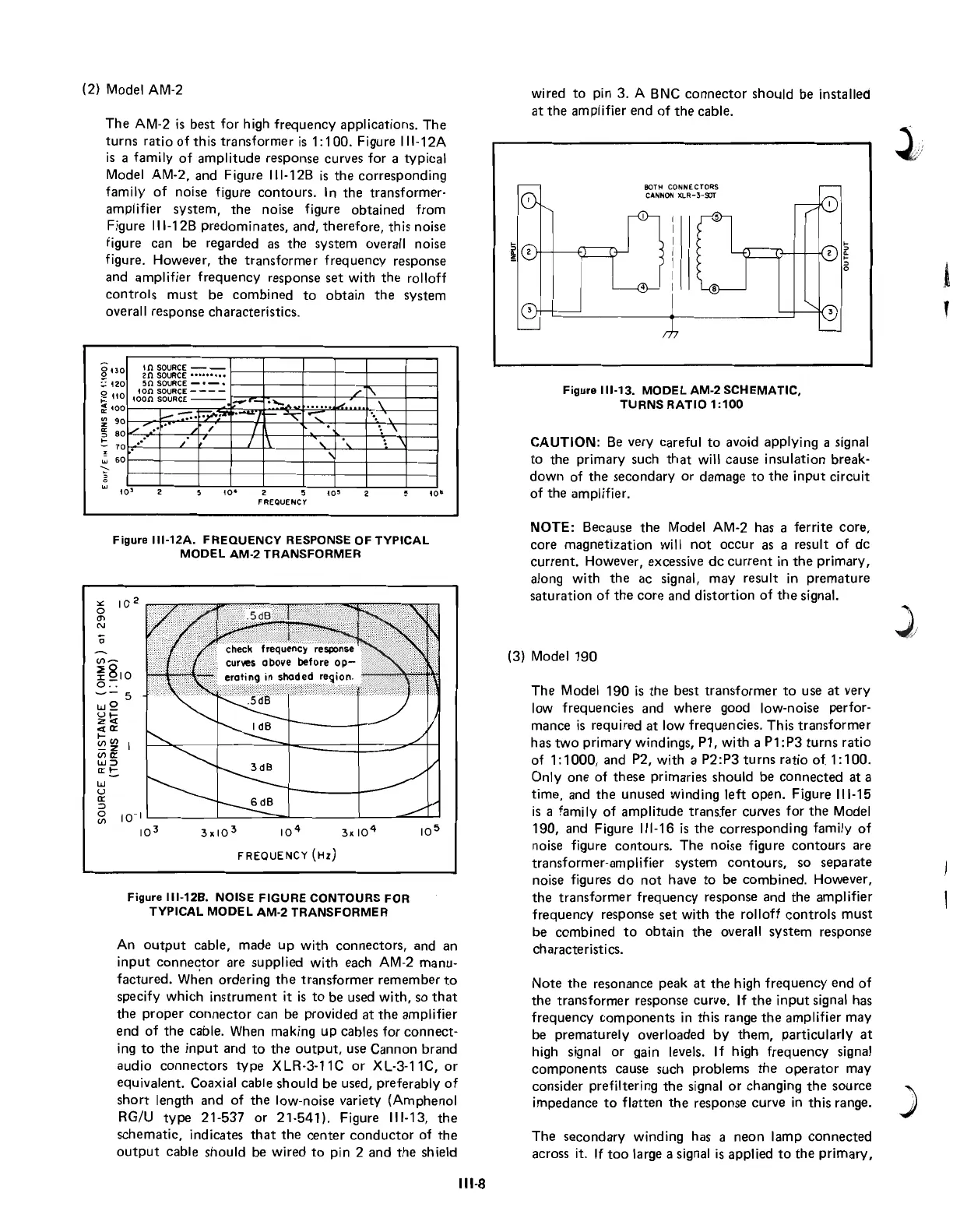
schematic, indicates
that
the
center
conductor
of
the
output
cable should be wired
to
pin 2 and
the
shield
111-8
wired
to
pin 3. A BNC
connector
should be installed
at
the
amplifier
end
of
the
cable.
BOTH CONNE CTORS
CANNON
XLR
-3-9JT
Figure
111-13.
MODEL
AM-2
SCHEMATIC,
TURNS
RATIO
1
:100
CAUTION:
Be
very careful
to
avoid applying a signal
to
the primary such
that
will cause insulation break-
down
of
the secondary
or
damage
to
the
input
circuit
of
the amplifier.
NOTE: Because
the
Model AM-2 has a ferrite core,
core magnetization will
not
occur
as a result
of
dc
current.
However, excessive
dc
current
in
the
primary,
along with
the
ac signal, may result
in
premature
saturation
of
the
core and
distortion
of
the
signal.
(3) Model
190
The
Model
190
is
the
best
transformer
to
use
at
very
low frequencies and
where
good low-noise perfor-
mance
is
required
at
low frequencies. This
transformer
has
two
primary windings, P1, with a P1: P3
turns
ratio
of
1:
1
000,
and P2, with a
P2:P3
turns
ratio
of
1:
100.
Only
one
of these primaries should be
connected
at
a
time, and
the
unused winding
left
open.
Figure
111-15
is
a family
of
amplitude
transfer
curves
for
the
Model
190,
and Figure
111-16
is
the corresponding family
of
noise figure
contours.
The
noise figure
contours
are
transformer-amplifier system
contours,
so separate
noise figures
do
not
have
to
be
combined.
However,
the
transformer
frequency response and
the
amplifier
frequency response
set
with
the
rolloff
controls
must
be
combined
to
obtain
the
overall system response
characteristics.
Note
the
resonance peak
at
the
high
frequency
end
of
the
transformer
response curve. If
the
input
signal has
frequency
components
in this range
the
amplifier may
be prematurely overloaded
by
them,
particularly
at
high signal
or
gain levels. If high
frequency
signal
components
cause such problems
the
operator
may
consider prefiltering
the
signal
or
changing
the
source
impedance
to
flatten
the
response curve in this range.
The
secondary
winding has a
neon
lamp
connected
across it.
If
too
large a signal
is
applied
to
the
primary,
)
 Loading...