The Outer Shells 01‘ The input
BNC
COHHBCIOFS are
(4)
Core
Magnetization, Corresponding Distortion,
and
'
floating
off
ground
(see 190
schematic,
Figure Ill-17);
Degausging
to maintain the
common-mode rejection
properties
of
The Transffmer. d0 "0? C0"eC'I the iut-Cable
Shield
Excessive
current through
a winding
of
a transformer
Y0 The TTa"$f°TmeT C359 9T°U"d-
will permanently
magnetize
the
core of most
trans-
“I
formers.
This is
true
of the
Models
AM-1 and
190. The
Model
AM-2 has
a
ferrite core which
virtually will
not
9 permanently magnetize. All transformer
cores
saturate
Pl -_>
in magnetization
(=B)
after a given
winding current
@ N has
been
reached
(<1
H
"' no. turns x i - ma
netizin
- " 9 9
® $3 force, where
i
= current
through
winding). The voltage
~
’ induced
in
the secondary is proportional to
dB/dt,
so
P2 the
secondary
voltage is
distorted on
that part of
the
® _‘ Q .
.
.
®
curve
where
B
is
not
a
linear function of
H.
A
permanently
magnetized
core
saturates at a
lower
level
/77 of
H,
and thereby
reduces the maximum signal
current
Tggjfm sssesssem that
can
be
transformed without
distortion.
Figure
<,,.,.2,,,,,i,E,,,,.,,,, ,,,,s,,,,,.eE,,,,,,,t,,,,,';,,,,,,,,,2,,,,,,,, ,°,,,,,,,,_ Ill-19
shows
a
B-H
curve
and
waveforms
that graph-
"sE“""°°°“"°‘ 'mm°'°"""°""" ically
illustrate this core saturation
and corresponding
distortion.
Note that
the
B-H characteristic
is
actually
a
loop; curves
#1
and
#2
of
Figure lll-19A
are
only
i=ieu,ei|i_17_ MQDEL 190 SCHEMA-i-ic representative
”center
/ines"
of the
corresponding
loops.
Actually,
the
loops
are
usually “squarish ovals",
CAU-i-i0Ni Avoid passing excessive de Current with different
degrees
of
squareness for different core
through
the primary
of
this
tranformer. More
than {“ateria|57 blft the details of the |°°p5 ale "_°t °f
200 “A Wiii magnetize the eere_ Core magnetization interest
in this discussion, only the
general
situation of
will
cause
the
transformer
to
saturate
prematurely
for
the loops W'th respect to 5aturat'°n'
one polarity
of
ac signal, resulting
in
distortion
of
high-level
signals,
and
a magnetized transformer is
usually
noisy
and microphonic, causing low
level
§§$§§:li§ii@“?§§§§"“'°"
distortion
as well. See
paragraph
(4) for
a discussion of
A D
..//
cui=iv£s#i 0 2 as
"ceuren mics"
0F
INDIVIDUAL
B-H LOOPS _.__ _ _..9
$*TURATE|-7 "Kilo" “
this distortion and a procedure
for degaussing the
E ,
transformer. Do
not measure winding resistance
with
$‘Z’?i"é‘ii'2EB'
an
ohmmeter,‘
ohmmeter
current
is sufficient to
/ii3>i;;;~6~;i»;i§§E»i,~LTR~i>;i~;~,;,;ii;ivE=R-
magnetize
the
core.
A
H
T
2 I
IF CORE lS PERMANENTLY
MQGNETIZED
THE
SIGNAL
PAST
THIS POINT
SKTURATES
THE
WE,
$
TTMT
MAXIMUM
Sl_GNlL
...._
_
_
_ __
AMPLITUDE
IS REUJCED.
ASSUME
SIGNAL LEVEL IS
NOT LARGE ENOUGH TO MAKE
CORE
GO
INTO
THIS REGION
CURRENT SATURATES CORE ABOVE THIS
LEVEL
/lF
CORE
IS PERMANENTLY MAGNETIZED.
I
i . PRIMARY
CURRENT
i ‘ I i=
I slim!
B 1 ' _’
WHEREM =2wl
l
/'ZirurPEAK son
one POLARITY ONLY
conaesimoiiis a
or
PERMANENTLY
MAGNETIZED
5 cone
(WORKING
on
cuavcdlzi.
C ‘ i l
I
A
\ CORRESPONDING INDUCED
' SECONDARY
VOLTAGE I Q
D i 08/di
oi; iiilcosiiii
i \/ EXCEPT
IN DISTORTED
REGION
DISTORTED
REGION J9
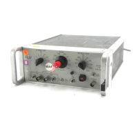
Figure Ill-18. PHOTOGRAPH
OF MODEL 190
TRANSFORMER
Figure
Ill-19.
B-H CURVE
&
WAVEFORM
lll-10
The
outer
shells of
the
input
BNC
connectors are
floating
off
ground (see
190
schematic, Figure
111-17);
to
maintain the common-mode rejection properties
of
the
transformer, do
not
connect
the
input-cable shield
to
the transformer case ground.
P
I
~
•
~
P2~
-
~
CASE
~
TERNINALl
NaTES :
I.
TURNS
RAllO
PI
:
P2:P3;.1:IO:10CX)
2.DC
RESISTANCE
PI8I42
",0;
P2S11l.SA; S3W32kA
3.
FREOt.£NCY
RESPONSE
(PI
DRIVEN
FROM
50
"'A
SOURCE
OR
P2
DRIVEN
FROM
5A
SOURCE) WITH ± ICl8
FROM
320
fillHI'
TO
500
Hr •
•.
SELf
INOJCTANCE
REFERRED
TO
PI-3
.
08_H
Figure
111-17.
MODEL
190 SCHEMATIC
s.
CAUTION: Avoid passing excessive
dc
current
through the primary of this tranformer. More than
200
pA
will magnetize
the
core. Core magnetization
will cause
the
transformer
to
saturate prematurely for
one polarity
of
ac signal, resulting
in
distortion
of
high-level signals, and a magnetized transformer
is
usually noisy and micropholJic, causing low level
distortion
as
well. See paragraph (4) for a discussion
of
this distortion and a procedure for degaussing
the
transformer.
Do
not
measure winding resistance with
an
ohmmeter;
ohmmeter
current
is
sufficient
to
magnetize
the
core.
A
....
PRINCETON
APPLIED
RESEARCH
MOOEl190
LOW
NOISE
TRANSFORMER
Figure
111-18.
PHOTOGRAPH OF
MODEL
190
TRANSFORMER
111
-
10
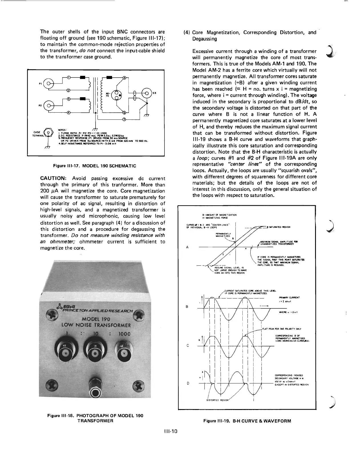
(4) Core Magnetization, Corresponding Distortion, and
Degaussing
Excessive current through a winding
of
a transformer
will permanently magnetize the core
of
most trans-
formers. This
is
true of
the
Models
AM-1
and 190.
The
Model AM.2 has a ferrite core which virtually will
not
permanently magnetize.
All
transformer cores
saturate
in magnetization (=B) after a given winding
current
has been reached
(0::
H = no. turns x i = magnetizing
force, where i = current through winding).
The
voltage
induced
in
the secondary
is
proportional
to
dB/dt,
so
the secondary voltage
is
distorted
on
that
part
of
the
curve where B
is
not
a linear function
of
H.
A
permanently magnetized core saturates
at
a lower level
of
H,
and thereby reduces the maximum signal
current
that
can be transformed
without
distortion. Figure
111-19
shows a
B-H
curve and waveforms
that
graph-
ically illustrate this core saturation and corresponding
distortion. Note
that
the
B-H
characteristic
is
actually
a loop; curves #1 and #2
of
Figure
11I-19A
are only
representative
"center lines"
of
the
corresponding
loops. Actually,
the
loops are usually "squarish ovals",
with different degrees
of
squareness for different core
materials;
but
the
details
of
the
loops are
not
of
interest
in
this discussion, only
the
general situation
of
the loops with respect
to
saturation.
8'
AMOJNT
CI
MAGNETIZATION
H •
MAGNETIZING
FOR(:(
CURVES# I a 2
ARE
"CENTER
LI
NES
"
OF
INDIVIDUAL
B-H
LOOPS
A
B
c
D
,---
ASSU-;';
SIGNAL
LEVEL IS
""
NOT
L.ARGE
ENOuGH
TO
MAKE
CORE
GO
I
NTO
THIS
REGION
,I'
COAE
IS
PERMANENTLY
MNlN(TlztO
THE
SIGNAl.
PAST
THIS
POINT
SA'NUm
THE
OOAE,
so
THill
IrIWtIMUM
SI,"Al
AMPLlTUOE IS
MOOCED.
•
PAt
....
fIY
CURRENT
ill
.....
t
WHERE
...
1
Z".t
I
I
FLAT
PEAK
FOR
ONE
POLARITY
ONLY
CORRE~DING
B
OF
PERMANENTLV MAGNETIZED
COM:
fWQflKING
ON
CURY£#2I-
CORRESPONOlNG INOUC€D
SECONDARY VOLTAQ£ •
CIt
dB/ dl
oc
...
1COh
,1
---t--
t--
----':r-;
-+----,t---
EXCEPT
IN DISTORTED REGION
D
IS
TO
RT
ED REGION
Figure
111-19.
B-H
CURVE
&
WAVEFORM
)
)
 Loading...