GB
- 27 -
5. Before starting the equipment
Before you connect the equipment to the mains
supply make sure that the data on the rating plate
are identical to the mains data.
Warning!
Always pull the power plug before making
adjustments to the equipment.
5.1 General information
•
The equipment must be set up where it can
stand securely, i.e. it should be bolted to a
workbench, a universal base frame or similar.
•
All covers and safety devices have to be pro-
perly fitted before the equipment is switched
on.
•
It must be possible for the blade to run freely.
•
When working with wood that has been pro-
cessed before, watch out for foreign bodies
such as nails or screws, etc.
•
Before you actuate the On/Off switch, make
sure that the saw blade is correctly fitted
and that the equipment‘s moving parts run
smoothly.
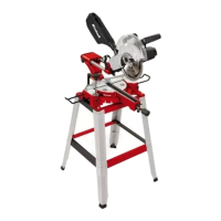
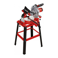
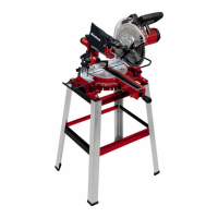
5.2 Assembling the saw (Fig. 1-5)
•
Fit to the locking screw (14) to the turntable
(17).
•
Fit the workpiece supports (10) on the left
and on the right of the fixed saw table (18).
Do this with the socket head screws (39) and
the 5mm hex key (40).
•
To fit the sawdust bag (22) to the discharge
opening (23) on the crosscut saw, spread the
metal ring apart on the opening. When the
metal ring is back in its original shape, the sa-
wdust bag is held securely in position.
•
The clamping device (8) can be fitted on the
left or right of the fixed saw table (18).
5.3 Adjusting the saw (Fig. 1-3)
•
To adjust the turntable (17), loosen the lo-
cking screw (14) by approx. 2 turns, which
frees the turntable (17).
•
Turn the turntable (17) and scale pointer (15)
to the desired angular setting on the dial (16)
and lock into place with the locking screw
(14). The saw has locking positions at angles
of - 45°, -31.6°, -22.5°, -15°, 0°, 15°, 22.5°,
31.6° and 45°, at which the turntable (17) au-
dibly clicks into position.
•
To release the saw from its position at the
bottom, pull the retaining pin (25) out of the
motor mounting while pressing down lightly
on the machine head (4).
•
Swing the machine head (4) up until the re-
lease lever (3) latches into place.
•
To adjust the machine head (4) for a miter cut,
slacken the locking lever (21).
•
Then you can tilt the machine head (4) to the
left by up to 45°. After the desired angular set-
ting has been set on the scale pointer (20) on
the scale (19), secure the machine head (4)
again with the locking lever (21).
•
To tilt the machine head to the right by up to
45°, proceed as follows:
- Tilt the machine head (4) by approx. 10° to
the left.
- Pull out and hold the button (33).
- Swing the machine head (4) over the 0°
line to the right.
- After reaching approx. 10° on the right-
hand side, let go of the button (33).
- When the pointer (20) reaches the desired
angular setting on the scale (19), secure
the machine head (4) again with the lo-
cking lever (21).
•
To return the machine head to 0° on the scale
(19) there is no need to press the button (33)
again.
•
To ensure that the saw is standing securely,
adjust the adjustable foot (13) by turning it so
that the saw stands in a horizontal and firm
position.
5.4 Precision adjustment of the stop rail
(Fig. 6)
•
Lower the machine head (4) and fasten in
place with the retaining pin (25).
•
Fasten the turntable (17) in 0° position.
•
Place the 90° stop angle (a) between the bla-
de (7) and the stop rail (11).
•
Slacken the four adjustment screws (42)
using the 5mm hex key (40), set the stop rail
(11) to 90° in relation to the saw blade (7) and
retighten the adjustment screws (42).
•
There is no angle stop (a) included the scope
of this delivery.
5.5 Precision adjustment of the stop for cros-
scut 90° (Fig. 7a, 8)
•
Fasten the turntable (17) in 0° position.
•
Slacken the locking lever (21) and tilt the ma-
chine head (4) to 0° using the handle (1).
•
Place the 90° angular stop (a) between the
blade (7) and the turntable (17).
•
Adjust the adjustment screw (26) until the
angle between the blade (7) and the turntable
(17) equals 90°.
Anl_TC_SM_2131_1_Dual_SPK9.indb 27Anl_TC_SM_2131_1_Dual_SPK9.indb 27 21.10.2019 09:47:1621.10.2019 09:47:16
 Loading...