TECNOEKA Srl ___________________________________________________________ operating and instruction manual
page 34 _____________________________________________________________________________________________
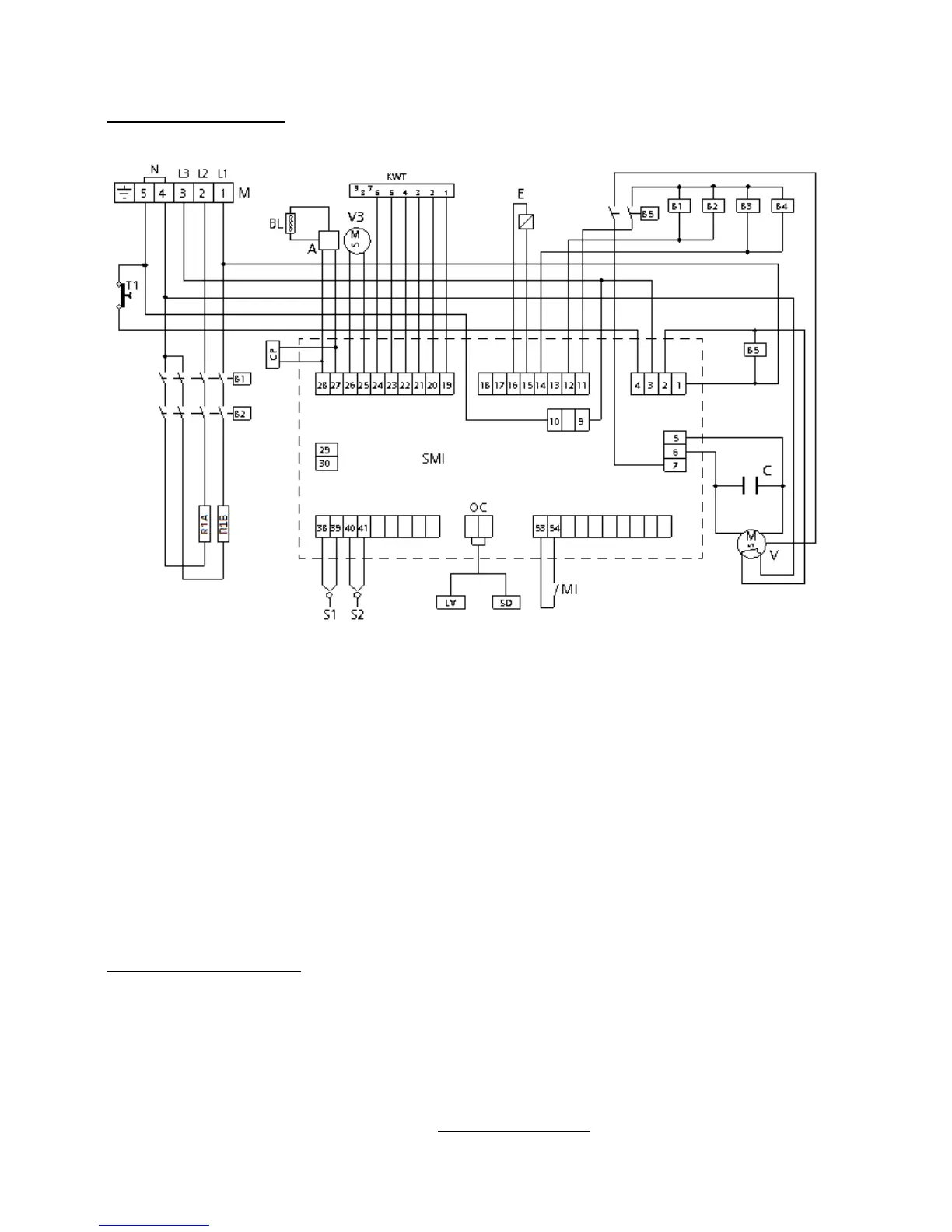
12 Wiring diagrams
13. Technical support
Before leaving the factory this appliance has been calibrated and tested by experienced and skilled
personnel in order to obtain the best operation results. Any repair or calibration must be carried
out with the utmost care and attention, solely using original parts.
That is why it is required to always contact the Dealer who has sold the appliance or our nearest
Technical Support Centre, specifying the kind of failure and the model of the appliance you have.
The parts required for adaptation to different types of gas are provided with the appliance hence
supplied upon sale or delivery. For servicing needs the user may contact Tecnoeka on the numbers
shown on the cover, or refer to the website www.tecnoeka.com.