E L A N H O M E S Y S T E M S
Page 4 © ELAN Home Systems 2009 • All rights reserved.
A2 INSTALLATION MANUAL
Chapter 2. System Design & Applications
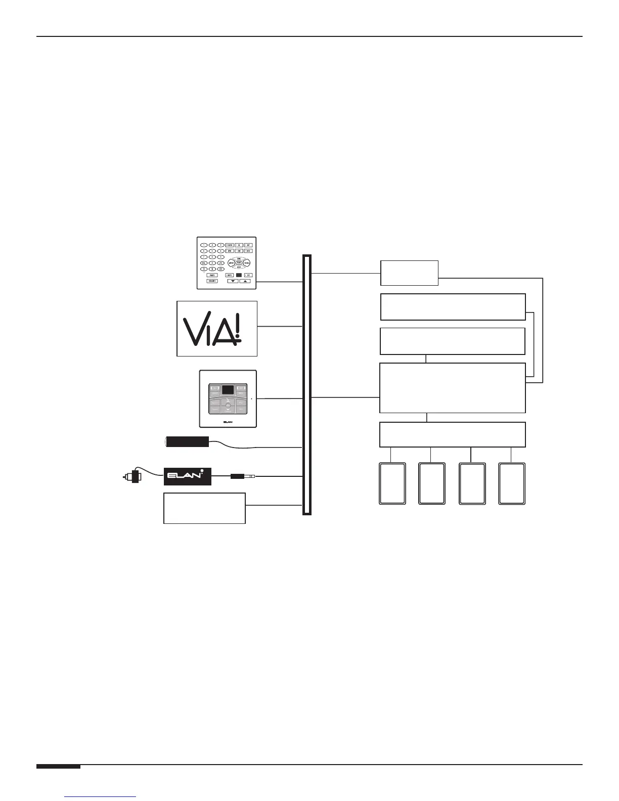
System Design
The first step to a good design is to map the system. It is advisable to mark up a copy of the house floor plan with
speaker, keypad, touch panel, volume control, and equipment locations etc. Make sure that all locations are decided
upon before pre-wiring commences so that all necessary wiring and installation hardware is in place. This unit will
be interfacing with other components such as multi-room controllers, source components, communications control-
lers, serial controllers, and user interfaces, so it is essential that ALL system components are accounted for prior to
the pre-wire stage.
Secondly, make a detailed list of all components. Include source equipment, keypads, touch panels, volume con-
trols, amplifiers, and communications gear. Be sure to include necessary electrical boxes, structured wiring enclo-
sures, telephone lines, rough-in brackets, patch cords, power supplies, etc.
TM
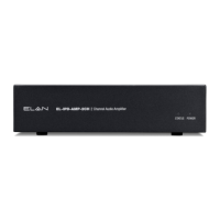
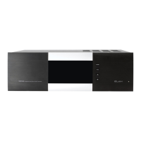
S66A
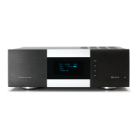
A2 Amplifier
C2
A/V Sources
SPP
(side view)
Sensors
External IR
Receivers
SS1
Keypads
AUDIO SENSOR
SPK SPK SPK SPK
Olé
Touchpads
FrontRear
Triggered
Devices
Figure 2-1: System Design
Pre-Wire
Wiring Considerations
• Speaker Wires 28-16 AWG Speaker Wire
• Audio Cables RCA Patch Cables
• Triggers 2 Conductor Wire w/ 3.5mm mono connector