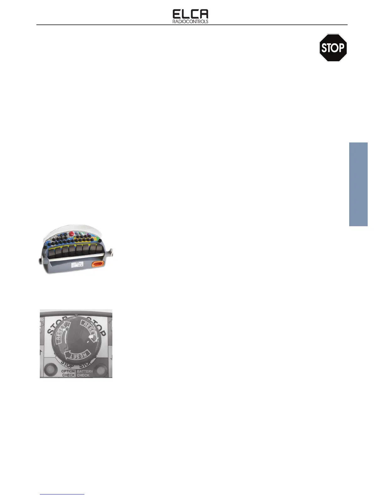
The receiving unit AT BRAVO-FUNK-915 comprises three main electronic circuits:
- RADIO TRANSMITTING BOARD. Containing all the electronics for the transmission and management of the working
frequency.
- INTERFACE CARD. Containing all the electronics for the management of the command inputs and signal encoding
- IDENTIFICATION CODE CARD. Containing the unique identication code of the system.
- TX EXTENSION CARD. Permits to increase the available commands.
The transmitting unit AT BRAVO-FUNK-915 univocally communicates with the receiver with its own receiver, because
the transmitted signal contains an identication code inside it that is not reproducible. Recognition of this code allows the
receiving unit to identify with certainty the unit that has transmitted the command. In this way any other device, different
or the same type, that is transmitting on the same frequency can not in any way replace the control of the machine to
which the system is connected. Any radio transmissions on the same working frequency as our transmitter or any radio
frequency disturbances can in the worst case only switch off the receiver with all outputs disabled (see description of
receiving unit operation).
When a new match key is mounted to the transmitter, it is necessary to perform the procedure for the acquisition of the
identication code. By means of the identication code acquisition procedure, the transmitter acquires the information
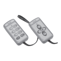
contained on the match key. The procedure is arranged for the Stop mushroom button to be activated with the transmitter
switched off; bring the starting keyswitch in position 1 and activate the Start command for approximately 10 seconds, until
the Battery Check LED ashes green. Any error signals are not to be taken into consideration in this precise instant. After
4.1 DESCRIPTION OF OPERATIONS
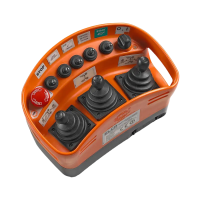
4. TRANSMITTING UNIT
the acquisition procedure, only the receiver with the hardware key containing the same
identication is enabled to activate the commands transmitted by the transmitter.
During normal use, when the keyswitch selector is brought into position 1, if the system
does not encounter abnormal conditions, the Battery Check LED starts rapidly blinking
green. When the Start command is pressed, the LED starts blinking slowly, to indicate that
the system is working.
With the keyswitch in position 1, the system runs checks on the status of the Transmitter
and, if it detects abnormal conditions, the following error statuses are displayed:
- Red Battery Check LED on for 2 seconds. The transmitting unit is not working properly or
the procedure for the acquisition of the identication code has not been activated.
- Red Battery Check LED on for 1 second. The Stop pushbutton has been detected as
being on or not working.
- Red Battery Check LED ashes 2 times. An ON/OFF command has been detected as
being on.
- Red Battery Check LED ashes 3 times. The battery has been detected as being low.
- Red Battery Check LED ashes 4 times. A joystick has been detected as out of position
zero.
Note. A sound signal is emitted when the red LED goes on.
During normal operation of the radio remote control, the red LED starts blinking when the
battery is low and approximately only 10 minutes of run time are left.
Certain ON/OFF functions or certain proportional functions can be installed during assembly
of the unit as functions that can be enabled when the transmitter is activated, without
generating an error condition. More detailed information on this type of commands can
be found in the documentation annexed to this manual that describes special customised
radio controls, built in accordance with precise technical specications of the customer.