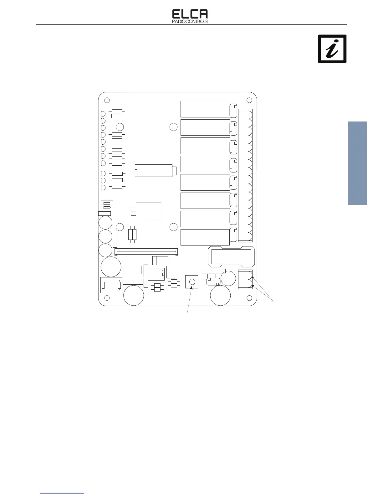
MOTHER CARD LAYOUT 8 RELAYS
LAYOUT SCHEDA BASE 8 RELE‘
+ + +
ON
+
K
K
K
K
K
K
K
K
K
K
K
+
-
+
+
Z2
C12
Z1
D7D1 D8D6D2 D3 D4 D5
RL2
RL4
RL6
RL7
RL5
RL3
RL1
RL8
C6C4
C3
DSW1
C7
C5
J2
C2
DL5
DL4
DL3
DL2
DL6
DL1
DL8
DL7
R4
R5
R6
R8
R7
R1
DL10
DL11
R11
DL9
R9
R10
R2
R3
R13
R12
U2 + VT1
U1
C1
J4
F1
R15
R17
R14
R16
C11
C10
C8
C13C9
U3
D9
L1
FL1
C14
PD1
C15
J3 + J5
J1 + J6
DT1 DT2
DT3
DT4
T4
T9
T11
START/T12
T3
T10
T2
STOP/T1
POWER
STATUS
LEARN
STOP/T1
START/T12
T11
T2
T10
T3
T9
T4
COM STOP / T1
NO STOP / T1
COM START / T12
NO START / T12
CO M T11
NO T11
COM T2
NO T2
COM T10
NO T10
COM T3
NO T3
COM T9
NO T9
COM T4
NO T4
1
2
FUSE 6.3A
CONNECTIONS TO
POWER SUPPLY
MORSETTI DI
ALIMENTAZIONE
DIP-SWITCH
CONNECTION TO GROUND
MORSETTO FILO TERRA
On “START/STOP Option„ mode, relay T12 is activated by pressure of START/STOP button and remains held until the
radio connection between transmitter and receiver is active, instead relay T1 operates just like any other command.
Nella congurazione “Opzione START/STOP„ il relè T12 si attiva alla pressione del pulsante START/STOP e rimane
ritenuto no a che il collegamento radio tra trasmettitore e ricevitore è attivo, mentre il relè T1 si comporta come un
normale comando.
ANNEX A