EasyManua.ls Logo

elco EK-TRON 5.300 G-E - User Manual

elco EK-TRON 5.300 G-E
38 pages
Print Icon
To Next Page IconTo Next Page
Loading...
09/09/2022 - Art. Nr. 420011267100
Original operating instructions
For specialist installation engineers
Gas burners
cn.......................................... 420011267200
EK-TRON 5.300 G-E (72H)
EK-TRON 6.350 G-E (72H)
EK-TRON 6.400 G-E (72H)
EK-TRON 7.500 G-E (72H)
EK-TRON 7.600 G-E (72H)
en
EK-TRON 5-6-7.xxx G-E
420011267300
EK-TRON 5-6-7.xxx G-E
420011xxxxx
EK-TRON 5.300 G-E KN
3148784
EK-TRON 5.300 G-E KM
3148325
EK-TRON 5.300 G-E KL
3148326
EK-TRON 6.350 G-E KN
3148785
EK-TRON 6.350 G-E KM
3148327
EK-TRON 6.350 G-E KL
3148328
EK-TRON 6.400 G-E KN
3148786
EK-TRON 6.400 G-E KM
3148329
EK-TRON 6.400 G-E KL
3148330
EK-TRON 7.500 G-E KN
3148787
EK-TRON 7.500 G-E KM
3148331
EK-TRON 7.500 G-E KL
3148332
EK-TRON 7.600 G-E KN
3148788
EK-TRON 7.600 G-E KM
3148333
EK-TRON 7.600 G-E KL
3148334
EK-TRON 5.300 G-E KN 72H
3148794
EK-TRON 5.300 G-E KM 72H
3148498
EK-TRON 5.300 G-E KL 72H
3148499
EK-TRON 6.350 G-E KN 72H
3148795
EK-TRON 6.350 G-E KM 72H
3148500
EK-TRON 6.350 G-E KL 72H
3148501
EK-TRON 6.400 G-E KN 72H
3148796
EK-TRON 6.400 G-E KM 72H
3148502
EK-TRON 6.400 G-E KL 72H
3148503
EK-TRON 7.500 G-E KN 72H
3148797
EK-TRON 7.500 G-E KM 72H
3148504
EK-TRON 7.500 G-E KL 72H
3148505
EK-TRON 7.600 G-E KN 72H
3148798
EK-TRON 7.600 G-E KM 72H
3148506
EK-TRON 7.600 G-E KL 72H
3148507
Question and Answer IconNeed help?

Do you have a question about the elco EK-TRON 5.300 G-E and is the answer not in the manual?

Overview

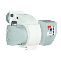
The ELCO EK-TRON 5/6/7.xxx G-E burners are electronically modulating, fully automatic monoblock burners designed for burning natural gas. They comply with standard EN676 and are intended for use in systems that meet EN 676 requirements. Special components are needed for use with heat generators under the Pressure Equipment Directive 97/23/EC.

Function Description:

These burners feature a special design of the burner head for highly efficient, low-polluting combustion. They are electronically modulating, allowing for stepless control of output across the entire range, from partial to full load. The fuel-air compound control system uniformly adjusts fuel and air volume, maintaining an optimum fuel-air ratio. Servomotors control the positions of the air and gas flaps, which are configured at the factory for minimum and maximum settings. During operation, these servocomponents precisely move to defined positions relative to burner output, ensuring low-emission combustion. The burner also includes a preventilation phase where the air flap opens to full load to ventilate the furnace and exhaust hoods. An automatic test for gas valve leaktightness is performed before each burner start. Ignition is achieved by a high-voltage spark at a gas injector, and a UV photocell monitors flame stability. The burner operates at minimum power after start-up, then modulates output based on heat demand. For enhanced efficiency, an optional O2/CO control system can be integrated, using an O2 measuring probe to adjust blower speed or air flap position, compensating for ambient variations and maximizing heating efficiency.

Important Technical Specifications:

  • Gas Train: Siemens VGD double valves for supply, shut-off, filtration, pressure regulation, and monitoring.
  • Gas Types: Gas families 1, 2, and 3 according to DVGW Worksheet G 260/1 and/or EN 437.
  • Max. Inlet Pressure: 500 mbar.
  • Electrical Connection: AC 220-240 V, 50 Hz.
  • Protection Level: IP 54.
  • Ambient Temperature: -10°C to +60°C.
  • Media Temperature: -15°C to +60°C (0°C to +60°C for liquid gas).
  • Servomotors: Schneider STE4.5, 24 VDC ±20%, 7.5 W power consumption, 90° angle of rotation.
  • Gas Pressure Switches: GW...A5/A6 types, IP 54 protection, -15°C to +50°C ambient temperature.
  • Boiler Lining: The burner must be installed at a right angle to the burner tube. The flame tube diameter (ØG) should be at least 70% of the combustion chamber diameter (ØDF). The space between the flame tube and boiler lining should be heat-resistant.
  • Ignition Electrodes: Specific dimensions for EK-TRON 5.300 G-... and EK-TRON 6.350 - 6.400 - 7.500/600 G-... models.

Usage Features:

  • Installation: Requires authorized specialists to ensure compliance with directives and regulations. Gas lines and trains must follow general installation regulations and national guidelines (e.g., SVGW, EKAS, DVGW-TVR/TRGI). Heavy gas train components should be fitted using suitable aids and lifting equipment. Tightening torques for screw connections must be observed, with specific values for accessories, terminal boards, fan impeller root connectors, and flange connections.
  • Commissioning: Before initial commissioning, a thorough check of the entire system is required, including boiler readiness, electrical wiring, motor rotation direction, safety device settings, gas connection pressure, leak-tightness of gas supply elements, and adequate air supply. The burner's electronic controller (BT320/BT330) manages the program sequence, including valve leaktightness check, fan operation, preventilation, air pressure regulation, ignition, and valve opening.
  • Safety Functions: Automatic flame monitoring, lockout in case of flame failure, air flow failure, or pressure failure. The burner control system indicates operational and fault messages. The gas leakage control for "E" version burners checks the leak-tightness of main gas valves.
  • Electromagnetic Field: The burner produces an electromagnetic field during operation, which may affect medical implants. Operators with implants should consult their doctor and implant manufacturer.

Maintenance Features:

  • Annual Inspection: A specialist should inspect the system at least once a year. A service contract is recommended.
  • Filter Replacement: Close the main gas valve, vent the pipe, loosen screws, remove and clean the filter element and housing. Replace with a new element, screw the cover back, reopen the valve, and check combustion values.
  • Cleaning: Clean the burner cover with water and a suitable cleaning product. The burner body should not be cleaned with hydrocarbon-based solvents.
  • Combustion Components: Check and clean the turbulator, gas nozzles, ignition transformer, electrodes, and cables. Replace worn or damaged parts.
  • Fan Wheel Setting: The turbine is designed for a fixed position on the drive shaft. Disassembly involves detaching the tie rod, removing air intake tubes, and loosening screws to remove the air case. Reassembly requires cleaning and degreasing surfaces, fitting the turbine to the axial stop, and tightening screws to 45Nm with LOCTITE 243. Damaged turbines must not be reused.
  • Exhaust Gas Measurement: Regular measurements are necessary to ensure efficient and low-polluting operation. The manual provides formulas and tables for calculating volumetric gas flow rate and determining excess air.
  • Troubleshooting: A comprehensive guide for diagnosing and remedying faults, including issues with flame response, combustion components, and solenoid valve failures. It outlines causes and remedies, such as cleaning dirty flame sensors, checking connections, replacing defective coils or automatic firing devices, and adjusting burner settings. In case of a gas smell, shut down the burner, close the gas valve, switch off the emergency switch, ensure ventilation, and notify the gas supplier. Components with technical safety-related functions should be replaced with original parts or parts of equal quality, not repaired.

elco EK-TRON 5.300 G-E Specifications

General IconGeneral
Brandelco
ModelEK-TRON 5.300 G-E
CategoryBurner
LanguageEnglish

Related product manuals