Assembly
ConnectingEquipment,FillingSystem
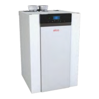
Sip
honandcondensatedischarge
I
nsertsiphon(1)accordingtheFigure
totheleft.
Dis
mountcoverpanelingfromcon-
densingboiler.
Con
nectcondensatedischargeand
neutralizingdevice(accessory)to
siphon.
Note:
Thecondensatelinemustnotbefirmly
connectedtothesewerline.The
condensatemustbeabletofreelydrip
intoafunnel.
Fillingsystem
Con
nectwaterhosetoKFEvalve(2).
O
penallradiatorvalves.
Fil
lcoldsystemupto1bar.
M
onitorwaterquality.
Ven
tilatepump(loosenimpellerwith
screwdriverifnecessary).
Fil
lcondensatesiphonwithwater
(approx.0.5l).
Sta
rtuppumpseveraltimes.
Upo
ncompleteventing,fillsystemto
finaloperatingpressure.
Clo
seventingscrewandremovefil-
linghose.
Replacingsystem
Rin
sesystemcarefully.
Che
ckconnectionsfortightnessand
leaks.
Ventilatesystemcarefully
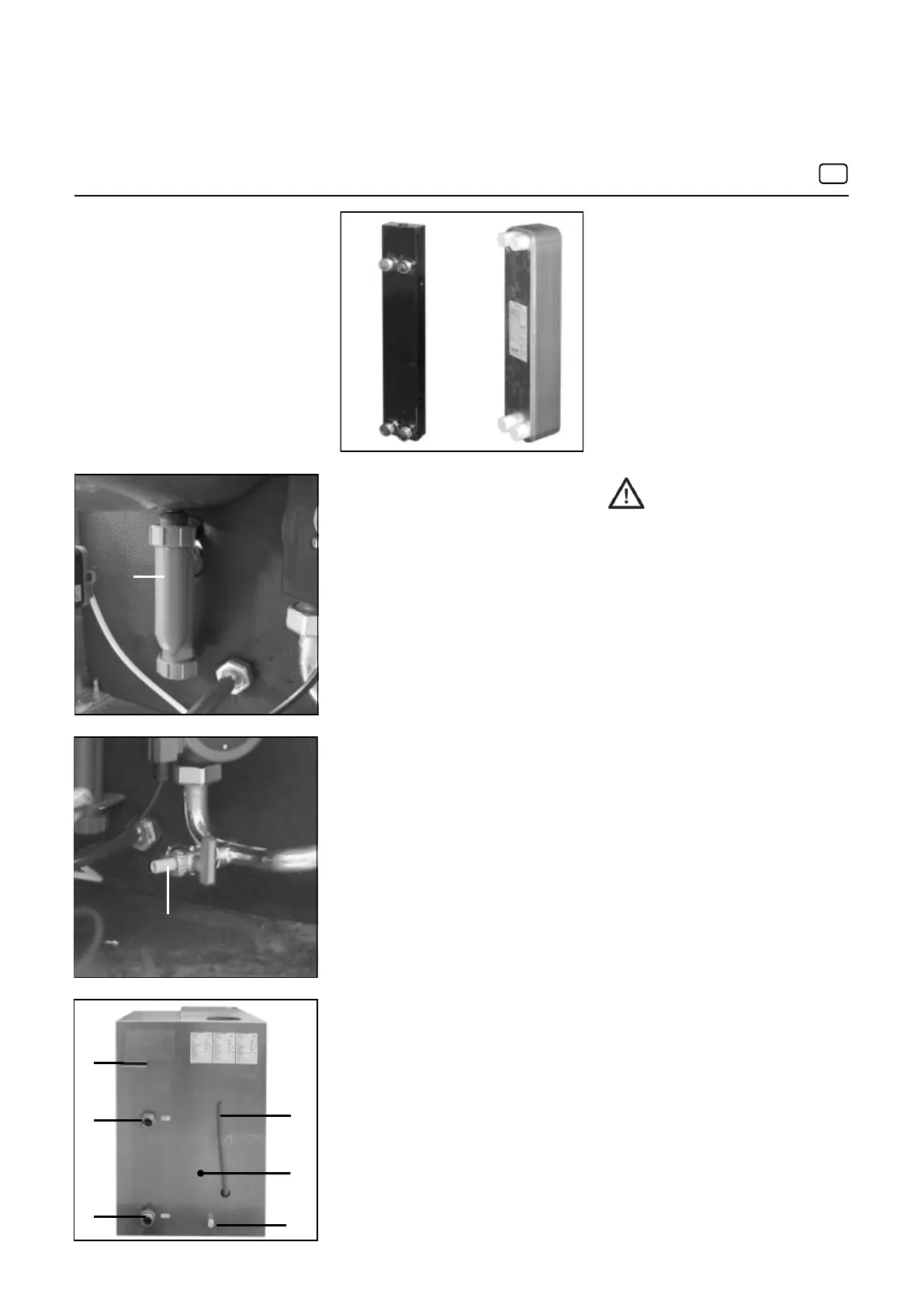
3 Cablepassageforexteriorcable
4 Gasconnector3/4“
5 Flowconnector
6 Returnconnector
7 Condensateconnector
8 expensionvessel
(plateheatexchangeronly)
14
1
2
3
5
6
7
8
4
Con
nectgasline
Che
cklinesfortightnessandleaks
Equipmentmustbeconnectedby
anauthorizedspecialistonly.
Pluginrequiredexhaustconnector
plate(concentric/parallel)
I
nsertboilerconnector(concentricor
parallel)fromthetopintotheintended
openingandpushintoreceivingpipe.
UselubricantsuitableforPPSex-
haustpipes
Con
nectexhaustcollectortoexhaust
system
M
ountconnectingpipe
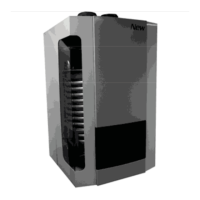
Installationofinternalhydraulic
accessories
Assemblyofthehydraulicswitchorthe
plateheatexchangerisperformed
followingaseparatemanual.
Thismanualiscontainedinthe
respectiveaccessoryset.
DANGER:
Dangerofpoisoning!Ifthe
siphonisnotfullofwater,orwith
openconnections,fluegasesarising
canputpeopleinmortaldanger.
e
n
 Loading...