11/2010 - Art. Nr. 4200 1029 8600A 13
Commissioning
Checks before commissioning
Adjustment data
Checking combustion components
Checks before commissioning
The following must be checked before
initial commissioning:
• That the burner is assembled in
accordance with the instructions given
here.
• That the burner is pre-set in
accordance with the values in the
adjustment table.
• Setting the combustion components.
• The heat generator must be ready for
operation, and the operating
regulations for the heat generator
must be observed.
• All electrical connections must be
correct.
• The heat generator and heating
system must be filled with water and
the circulating pumps must be in
operation.
• The temperature regulator, pressure
regulator, low water detectors and any
other safety or limiting devices that
might be fitted must be connected and
operational.
• The exhaust gas duct must be
unobstructed and the secondary air
system, if available, must be
operational.
• An adequate supply of fresh air must
be guaranteed.
• The heat request must be available.
• Fuel storage tanks must be full.
• The fuel supply lines must be
assembled correctly, checked for
leaks and bled.
• A standard-compliant measuring point
must be available, the exhaust gas
duct up to the measuring point must
be free of leaks to prevent anomalies
in the measurement results.
The settings data below are basic
settings. The factory settings data is
highlighted in bold and with a grey
background. With a normal case, these
settings enable the commissioning of
the burner. In all cases, carefully check
the settings values. In most cases,
according to the installation, corrections
must be made.
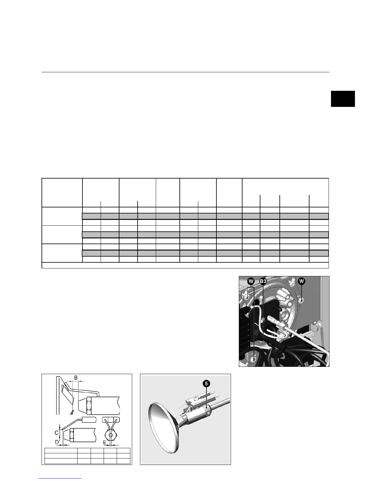
Checking checking combustion
components
• Disconnect the ignition cable on the
transformer side.
• Loosen the nozzle supply line.
• Loosen the three cover screws W.
• Remove the cover and remove the
mixture ignition device.
• Check nozzle sizes and exchange in
accordance with the parts specified in
the above table if necessary.
• Check the adjustment of the ignition
electrodes block and the baffle plate
and adjust if necessary.
• Check the gap between nozzle and
baffle plate and adjust if necessary.
1. stage 2. stage 1. stage 2. stage 1. stage 2. stage
60 80 5 7 1,35 11 22 20 30 30 40 50
70 100 6 8 1,50 11 22 30 30 30 40 60
90 120 8 10 2,00 11 22 35 35 35 40 60
80 110 7 9 1,75 11 21 25 30 30 40 50
100 140 8 12 2,25 11 22 30 35 35 40 90
110 160 9 13 2,50 11 22 35 35 35 40 90
100 140 8 12 2,25 11 22 15 35 35 40 70
125 170 11 14 2,75 11 22 20 40 40 65 90
150 210 13 18 3,00 11 21 35 50 50 65 90
Burner
2. stage
Stage
changeover
Ignition
Combustion head settings
Head setting values (space between
nozzle and turbulator - dimension B,
space between nozzle and ignition
electrodes - dimension C) can be
checked with enclosed drawing. The two
dimensions are set in the factory.
Dimension B was set thanks to adjust
ring 5. While reassembling the turbulator
for a nozzle replacement, it is not
necessary to re-adjust dimension B, as
far as the turbulator is re-assembled on
the stop on ring 5.
 Loading...