B
bushamandaAug 8, 2025
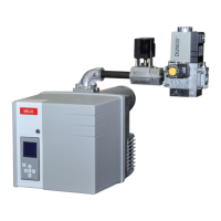
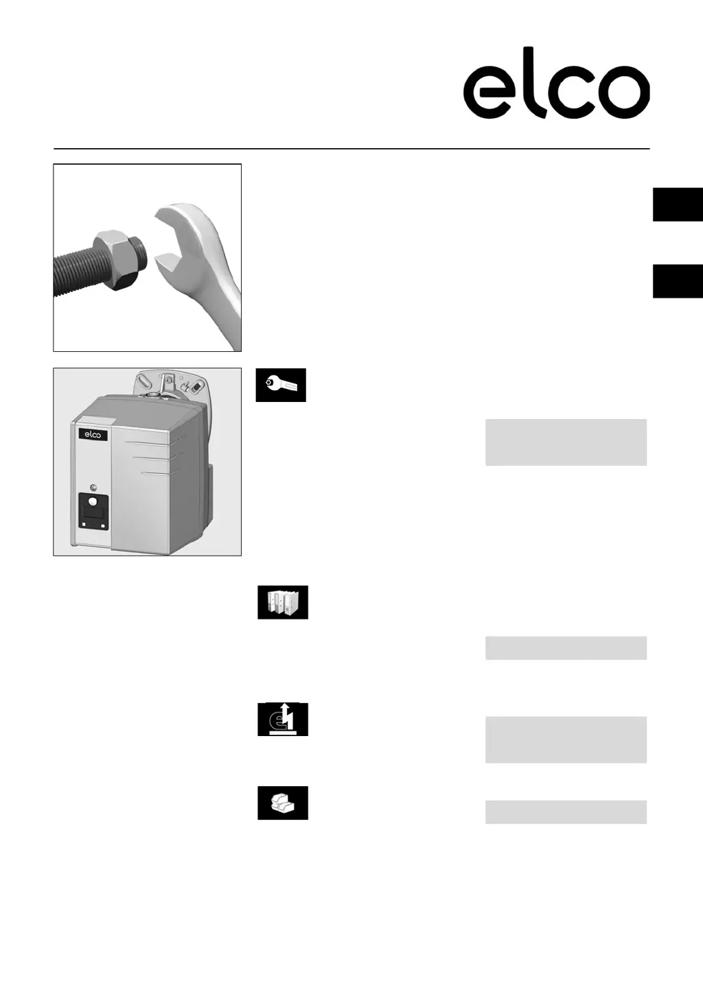
Why elco VG 1.40 Burner does not start with normal gas pressure?
- MMr. Caleb MooreAug 8, 2025
If the Elco Burner does not start, but you have normal gas pressure, it might be due to insufficient gas pressure or a gas pressostat that is wrongly set or defective. To resolve this, check the gas lines, clean the filter, and inspect or replace the gas pressostat or the compact gas unit.