This document provides a comprehensive guide for the Elco Vectron G 1.40, G 1.55, and G 1.85 forced-draught gas burners, intended for specialist installation engineers. It covers installation, commissioning, operation, and maintenance, ensuring safe, environmentally sound, and energy-efficient performance.
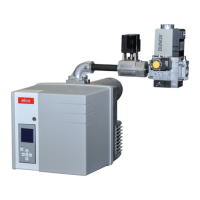
The Vectron G 1.40/55/85 burners are single-stage, fully automatic, monoblock type burners designed for low-pollutant combustion of natural gas and Liquefied Petroleum Gas. Their special burner head design ensures high efficiency and low emissions, complying with EN676 standards, including emission class 3, and national environmental legislation. The burners are suitable for use with various heat generators, including those complying with EN 303, DIN 4794, and DIN 30697. Any other application requires Elco's approval. Assembly and commissioning must be performed by authorized specialists, adhering to all applicable guidelines and directives.
The scope of delivery includes the burner, a gas connection flange, a compact gas train with a gas filter, a burner flange with insulation, and a bag of installation fittings. Technical documentation is also provided.
For safe and efficient operation, the following standards must be observed: EN 676 for forced-draught gas burners, EN 226 for connecting vaporizing oil and forced-draught gas burners to heat generators, and EN 60335-2 for the safety of electrical equipment for domestic use. Gas line routing and gas train installation must comply with general installation regulations and national guidelines, such as SVGW gas directives G1 and EKAS Form. 1942 in Switzerland, and DVGW-TVR/TRGI in Germany.
The burner should not be installed in rooms with aggressive vapors (e.g., hairspray, tetrachloroethylene, carbon tetrachloride), high dust levels, or high air humidity (e.g., laundry rooms). An adequate air inlet must be present, with specific size requirements depending on the country and burner power.
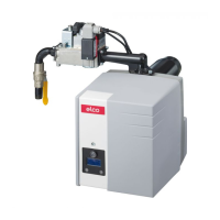
The compact gas units, VR4625 and MB-DLE 407, integrate gas pressure regulation and are suitable for single-stage forced-draught gas burners. The VR4625 is registered under CE-0063AP3090, and the MB-DLE 407 under CE-0085AP3156. Both units operate by opening valves Y12 and Y13 when voltage is applied to their magnet coils. An upstream fine screen protects the valve seating from contamination, and an installed pressure regulator controls the desired outlet pressure. Adjustment values for the gas pressostat, gas pressure regulator, and initial gas pressure can be set using adjusting screws, and inlet/outlet pressures can be measured at designated nipples.
The TCG 1xx automatic gas combustion control unit manages and monitors the forced-draught burner. Its microprocessor-controlled program ensures stable time periods despite power supply or ambient temperature fluctuations. It is designed to handle brownouts and extreme power failures, shutting down if the supply voltage drops below the minimum rated level and restarting once normal levels are restored. The control unit can be locked (malfunction) or unlocked (malfunction cleared) by pressing the R reset button while connected to the mains. Always disconnect power before installing or removing the control unit, and do not attempt repairs.
The burner assembly involves securing the burner flange to the boiler using screws, fitting the pipe bracket to the burner pipe, and guiding the burner into the flange. The burner flange has elongated holes compatible with various hole circle diameters (150-170 mm), complying with EN 226. The burner flange gasket and fastening screws are included. The pipe bracket allows adjustment of the combustion head's installed depth to match the combustion chamber geometry. This depth remains consistent during fitting and removal, and the bracket secures the burner to the connecting flange and boiler, ensuring a complete seal of the combustion chamber. For removal, loosen a screw, turn the burner out, and pull it from the flange.
When connecting gas lines and trains, ensure sufficient space for access to adjusting points and thoroughly bleed the gas supply line. All connections must be checked for leaks. For Liquefied Petroleum Gas (LPG) operation, the natural gas shutter must be replaced with an LPG shutter. This involves removing the gas head, loosening the baffle plate, installing the LPG shutter with the stamp facing upwards, and refitting the gas head.
Electrical installation and connection must be performed by an authorized specialist, adhering to all rules and regulations. Verify the power supply voltage (230 V, 50 Hz) and ensure a 10 A burner fuse is used. The burner and heat generator connect via a 7-pin connector. The compact gas unit connects to the burner terminal block via two prewired connectors. In Switzerland, a gas safety valve must be installed in the main gas inlet pipe according to SVGW guidelines, and in Germany, gas-fired installations require a thermally triggered shut-off valve.
Before commissioning, perform checks and inspections: verify the heat generator manufacturer's operating instructions, set temperature and pressure regulators, limiters, and safety guards, ensure minimum gas connection pressure (20 mbar flow pressure), check for leaks in gas supply elements, vent fuel supply pipes, and confirm open flue gas ducts and adequate fresh air supply.
The burner program sequence test without flame formation is initiated by the control unit's sealing test, which requires gas pressure. To check the entire sequence without flame, close the gas manual shut-off valve after the sealing test. Open the manual shut-off valve, activate the boiler controller, follow the sealing test display, and close the manual shut-off valve again once the second valve opens. The program will run until a safety shutdown (malfunction lamp lights up) due to the safety period expiring or gas shortage. Disconnect power, open the manual shut-off valve, re-supply power, unlock, and restart.
Ionisation current measurement is performed at the designated measuring point. Remove the measuring bridge and connect a multimeter with a 0-100 μA range. The monitoring current must be at least 8 μA.
Air regulation is performed at two points: on the ventilator's pressure side via an air metering drum and in the burner head via the baffle plate and burner pipe nozzle. The air metering drum has a linear regulating characteristic, operated by a regulating knob, with the value checked on the control dial. Adjusting the burner head's baffle plate influences airflow, mixing zone, and air pressure in the burner pipe. Turning a screw clockwise reduces air, and anti-clockwise increases it. The air intake adjuster is factory-set to 1 (max. blower pressure). If a higher blower pressure is disadvantageous, it can be reduced by loosening an adjustment screw, setting the adjuster to a new value, and re-tightening the screw.
For the VR4625 compact gas unit, loosen screw plugs at measuring points 119 and 119 pBr and connect measuring devices. The pressure regulator (screw C) is factory-set and sealed. If the gas pressure is incorrect, adjust the burner head and air flap according to the table, remove the protective cap on the pressure regulator, and turn screw C (clockwise for more power, anti-clockwise for less power). The full adjustment range is 10 turns (one turn = 60 daPa). Set pressure pBr via screw C and measure gas pressure at points 119 and 119pBr.
For the MB-DLE407 compact gas unit, the adjusting screw has 60 turns for output pressure adjustment (three turns clockwise/anti-clockwise change pressure by 1 mbar). At commissioning, turn the screw at least 20 turns clockwise, and the gas pressure downstream of the regulator should be 12-15 mbar (measured at the gas pressostat measuring nipple 119.1). For initial load flow adjustment, twist off the protective cap and use it as an adjustment tool. Turn the spindle towards the minus symbol, then back to the middle position (approximately 3 half turns) to set the initial gas flow to half open. Adapt the initial gas flow to the heat generator's pressure characteristics for smooth start-up. For rated load setting, loosen the locking screw to adjust the rotary knob (do not loosen the sealed screw on the opposite side). Reduce main flow by turning the knob clockwise or increase it anti-clockwise. The total path from minimum to maximum flow is approximately 4.5 turns. Re-tighten the locking screw and measure gas pressure at 119pBr.
To optimize combustion values, adjust the baffle plate's position (dimension Y). This affects starting characteristics, pulsation, and combustion values. Reducing Y increases CO2 but makes starting harsher. Compensate for airflow changes by adjusting the air flap position. Always observe the minimum required flue gas temperature specified by the boiler manufacturer and the requirements for flue gas ducts to prevent condensation.
To check controllability, operate the burner at rated load, measure gas pressure at points 119 and 119pBr. Slowly close the ball valve upstream of the compact unit until the gas input pressure at 119 falls to 20 daPa. The gas outlet pressure at 119pBr must not fall by more than 10%. If it does, check and correct the setting. The system must not be operated if controllability is insufficient. Open the 90° manual shut-off valve.
For the gas pressostat, remove the cover, connect a measuring device, and start the burner. Reduce upstream gas pressure by closing the manual shut-off valve until downstream pressure reduces to 70%, flame stability decreases, CO value increases, or flame signal worsens. Turn the dial clockwise until the gas pressostat shuts down the burner, then turn it clockwise again to set the gas pressostat 10% above the predetermined shutdown value. The adjustment value must be higher than blower pressure but lower than gas pressure downstream of the gas valve. Check the switch-off point by opening and closing the manual shut-off valve during burner start. The gas shortage program should start without triggering a safety shutdown.
For the air pressure switch, the factory setting is 1.0 mbar. Test and reset the switching point during adjustment. Install a T-piece in the pressure tube for the measuring device, switch on the burner, and adjust the switching point approximately 15% below the triggering pressure.
An operating check of flame monitoring is crucial for safety during initial commissioning, after servicing, or if the system has been out of operation for a significant period. With the gas valve closed, the automatic combustion control unit should switch to gas shortage or malfunction after the safety period. With the air pressure switch closed, the burner switches to malfunction after an 8-second test time. With the air pressure switch open, the automatic firing device switches to malfunction after a 60-second wait time. If the air pressure switch is briefly open during pre-ventilation, the firing device restarts the pre-ventilation program if air pressure builds up again within 60 seconds; otherwise, a safety shutdown is triggered.
Maintenance must be carried out by a trained heating specialist. A service contract is recommended for regular servicing. Always disconnect electrical supply and close the gas shut-off valve before any maintenance or cleaning. Regularly check flue gas temperature and clean the boiler if the temperature is more than 30 K above the commissioning value. Use a flue gas temperature indicator for simplified checks.
For burner maintenance, remove screws to hang the equipment plate in maintenance positions. To disassemble the gas head, remove the lock nut, screw in the dome nut, pull out the gas pipe, and undo ignition and ionisation cables. When refitting, ensure correct cable routing and properly seated O-rings. Maintenance work includes checking gas supply components for leaks or wear, checking electrical connections and cables for damage, cleaning/replacing the gas filter, cleaning the blower wheel and housing, cleaning the mixing unit, checking/readjusting/replacing ignition electrodes, checking flue gas data and burner settings, checking air pressure switch and gas pressostat settings, and checking gas train controllability. Perform an operating check.
When replacing the motor and blower wheel, observe the positioning diagram: the inside flange of the blower wheel must be at the same level as the equipment plate. Use a straight edge to set the blower wheel wings to the same height as the equipment plate, then tighten the set screw on the blower wheel.
The maintenance frequency indicator displays information after a certain period of operation. A wrench symbol indicates that maintenance is due. If the fitter has registered their telephone number, it will appear, along with the service contract number. To change the telephone or contract number, access the fault menu by pressing BP1, scroll to the desired pictogram, press BP2 to enter edit mode (first figure flashes), select the value with BP1, confirm with BP2, and repeat for all figures. After confirming the last figure, the pictogram displays for 5 seconds before returning to the operating screen.
In case of malfunction, first check basic prerequisites: power supply, gas pressure, open gas shut-off valve, and correct adjustment of all control and safety devices. If the malfunction persists, use the troubleshooting table. Safety-relevant components must not be repaired but replaced with original spare parts. After any operation, check combustion under normal conditions and inspect lines for leaks. Record all results in relevant documents.