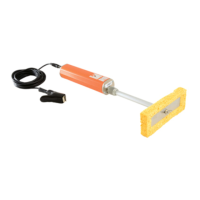
Turn ‘Voltage’ up slowly and steadily until a spark is
produced.
Note the voltage. This voltage forms the lower limit.
5.2.2 The Upper Limit.
The upper voltage limit is the dielectric strength of the material
multiplied by its thickness.
The following are methods for determining the upper voltage
limit.
The job specification - if available and a test voltage is stated.
The dielectric strength - if specified for the applied coating.
Measure the thickness of the layer and refer to Figure 5.
Alternatively, calculate the maximum voltage, allowing for
variations in the coating thickness. Note that 1kV per mm is
equivalent to 25.4V per mil/thou. This method is only suitable
if the dielectric strength values were determined for a DC
voltage.
Experimentation - touch the probe on an unimportant area of
the work piece. Increase the voltage slowly and steadily until
a spark passes through the coating. Note the displayed
voltage. The dielectric strength can be calculated by dividing
the voltage by the material thickness.
Tables and formulae - from established Codes of Practice,
e.g. NACE and ASTM. See Tables 2, 3 and 4.
5.3 Setting Alarm Sensitivity.
Sensitivity determines the point above which the alarms are
triggered when a flaw is detected. It is adjustable to allow for
the effects of any electrical leakage, through the coating or
moist air, which would unnecessarily trigger the alarms.
11