Home
Elcometer
Security Sensors
136
Elcometer 136 User Manual
4
of 1
of 1 rating
27 pages
Give review
Manual
Specs
To Next Page
To Next Page
To Previous Page
To Previous Page
Loading...
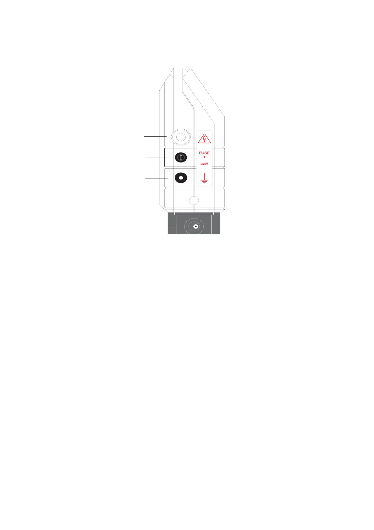
3.2
Connections
and
Terminals.
Figure
3
-
Side
Connections
and
Terminals
Layou
t
1.
High
voltage
pro
be
connection
2.
Fuse
and
fuse
holder
(1.6A
T-typ
e
fuse,
supplied
separa
tely)
3.
Earth
lead
terminal
4.
Nut
securing
battery
pack
5.
Slide-out
batt
ery
pack
6.
Battery
char
ger
connection
À
Á
Â
Ã
Ä
1.6 A
4
8
10
Table of Contents
Table of Contents
3
Safety Guide
6
Do Not
6
Introduction
8
Equipment Identification
8
Control Panel
8
Connections and Terminals
9
Detailed Operation
10
Test Batteries
10
Connect Leads
10
Select Probe
11
Earth to Substrate
11
Check the Earth Connection
11
Set the Test Voltage
12
Set Alarm Sensitivity
12
Detecting Holidays and Other Coating Flaws
12
Moving Work Position and Finishing Work
12
Static Electricity
13
Test Voltage & Sensitivity
14
Dielectric Strength
14
Determining the Voltage Limits
15
The Lower Limit
15
The Upper Limit
16
Setting Alarm Sensitivity
16
Probe Selection
18
Troubleshooting
18
LCD Display Related Problems
18
Alarm Related Problems
19
Special Considerations
20
Conductive Coatings
20
Concrete Substrates
21
Maintenance
22
Battery Maintenance
22
Charging the Battery
22
Replacing the Battery
22
Deep Discharged Battery
23
Lengthening the Earth Lead
23
Routine Checks
23
Probe, Spares and Accessories Guide
24
Right Angle Probes
24
Spare Electrodes for Right Angle Probes
24
Circular Brush Probes
25
Rolling Spring Probes
26
Extension Pieces
27
Spares Numbers
27
4
Based on 1 rating
Ask a question
Give review
Questions and Answers:
Need help?
Do you have a question about the Elcometer 136 and is the answer not in the manual?
Ask a question
Elcometer 136 Specifications
General
Brand
Elcometer
Model
136
Category
Security Sensors
Language
English
Related product manuals
Elcometer 270
56 pages
Elcometer 266
44 pages