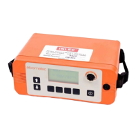
The Elcometer 136 DC Portable Holiday Detector is a specialized instrument designed for detecting flaws in non-conductive coatings applied to conductive substrates. This device is crucial for quality control in various industries, ensuring the integrity of protective coatings.
Function Description
The Elcometer 136 operates by applying a high DC voltage to the coating surface via a probe. The substrate beneath the coating must be conductive and properly earthed to the detector. When the probe encounters a flaw (a "holiday") in the coating, the electrical circuit is completed, triggering both an audible and a visual alarm. A spark may also be produced at the flaw location. This method allows for the identification of pinholes, cracks, and other discontinuities that could compromise the coating's protective function.
The detector is designed for use on coatings that are at least 200 microns (0.008") thick, with optimal performance on coatings over 500 microns (0.020") thick. For thinner coatings (between 200 and 500 microns), the wet sponge method with other Elcometer models (204 and 269) is recommended. The device generates a high voltage at the probe tip, up to 30,000 volts, requiring extreme care during operation as touching the probe can result in a mild electric shock, though typically not dangerous due to low current.
Important Technical Specifications
- Output Voltage: Up to 30kV (30,000 volts) DC.
- Coating Thickness Suitability: Minimum 200 microns (0.008"), preferably over 500 microns (0.020").
- Battery Life: Approximately 8 hours of continuous use.
- Battery Recharging Time: 10 hours.
- EMC Compliance: CE marked, meeting directives 89/336/EEC, amended 92/31/EEC & 93/98/EEC.
- RF Emissions: Generates broadband RF emissions (approx. 60dBuV/m from 30MHz to 1000MHz at 3m distance during continuous sparking) when a spark is produced. It is recommended not to operate within 30m of sensitive electronic equipment.
Usage Features
The Elcometer 136 features a user-friendly control panel with an LCD display for output voltage, a voltage control knob, an ALARM indicator (visual alarm), ON/OFF/Test buttons, a sensitivity control knob, and a battery level indicator.
Safety Guidelines (Do Not):
- Do NOT use in combustible, flammable, or explosive atmospheres.
- Do NOT carry out tests close to moving machinery.
- Do NOT use in precarious, wobbly, or elevated situations without a safety harness.
- Do NOT use in rain or damp atmospheres.
- Do NOT use if you have a pacemaker or heart condition.
- Do NOT clean the instrument or cables with liquids; cleaning for overspray/spots is a service requirement.
Safety Guidelines (Do):
- Do read the instructions carefully before use.
- Do consult the plant or Safety Officer before testing.
- Do wear rubber gloves.
- Do undertake testing clear of other personnel.
- Do work with an assistant to keep the test area clear.
- Do check for solvents or ignitable materials in the test area, especially confined spaces.
- Do switch off and disconnect leads when work is finished or unattended.
- Do ensure the earth lead is connected to the conducting substrate before switching on.
- Do only use on cured, thickness-tested, and visually inspected coatings.
- Do be aware of static build-up; wear rubber gloves and take special care in confined areas.
Detailed Operation:
- Battery Test: Turn 'Voltage' fully anti-clockwise to zero. Press [ON]. Check the battery level indicator (black segments from 'F' to 'E'). If no segments, recharge/replace.
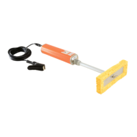
- Connect Leads: Press [OFF/Test]. Turn 'Voltage' fully anti-clockwise. Connect the red high voltage probe handle and lead to the high voltage probe connection. Connect the earth lead (green connector, green and yellow wire) to the earth lead terminal.
- Select Probe: Choose the appropriate probe based on the surface type (Table 1 provides guidance).
- Small, complex areas: Band brush probe (low contact pressure).
- Large surface areas: Right-angle brush probe (various widths, conductive rubber strip for light contact, phosphor bronze wire for medium contact).
- Inside pipes (38-305mm diameter): Circular brush probe (phosphor bronze, with 250mm extension).
- Outside pipes (50-1000m diameter): Rolling spring probe (phosphor bronze, with 250mm extension).
- Earth to Substrate: Clamp the earth lead to the exposed substrate.
- Check Earth Connection: Hold the probe in free air, press [ON]. Turn 'Voltage' clockwise until '1kV' is displayed, then 'Sensitivity' fully clockwise. Place the probe on bare substrate or the earth connection. Alarms should sound and light up, and the neon light in the probe handle should glow, indicating a good connection. If not, repeat this section or refer to troubleshooting.
- Set Test Voltage: Hold the probe in free air, press 'ON'. Turn 'Voltage' clockwise to the required test voltage. The manual provides background information on determining appropriate voltage limits based on dielectric strength and coating thickness (Figure 5, Tables 2, 3, 4).
- Lower Limit: Voltage required to break down an equivalent thickness of air (1.3 to 4kV/mm multiplied by thickness). Can be determined experimentally by increasing voltage over an uncoated area until a spark is produced.
- Upper Limit: Dielectric strength of the material multiplied by its thickness. Can be determined from job specifications, dielectric strength values (Figure 5, 1kV/mm = 25.4V/mil/thou), experimentation (sparking through an unimportant area), or established Codes of Practice (NACE, ASTM).
- Set Alarm Sensitivity: Use the 'Sensitivity' control. Fully clockwise provides maximum detector sensitivity and lowest threshold current. Fully anti-clockwise provides minimum detector sensitivity and highest threshold current. This adjustment helps avoid false alarms from electrical leakage.
- Detecting Flaws: Place the probe on the test surface, maintaining contact, and move it at approximately 0.25m/s (10"/s). Flaws are indicated by a spark, flashing 'ALARM', audible alarm, a substantial drop in output voltage on the LCD, and the probe neon indicator glowing.
- Moving Work Position/Finishing Work: Always turn off the detector and set voltage to zero before disconnecting leads. Recheck earth connections after moving.
Maintenance Features
- Battery Maintenance: The Elcometer 136 uses a sealed gel battery that should be stored charged. Battery life is typically 8 hours, with a 10-hour recharge time. Spare batteries are recommended for usage exceeding 8 hours in 24.
- Charging the Battery: Remove the detector from its carry case. Loosen bolts on each side to remove the battery. Connect the charger to the battery (terminals side up). Plug into mains. Red indicator shows charging; green with red indicates full charge. Charge for 10 hours.
- Replacing the Battery: Remove detector from carry case, loosen bolts, remove battery. Check and gently lever up flattened battery connectors with a screwdriver. Ensure detector is off and 'Voltage' is fully anti-clockwise. Insert new/recharged battery with correct polarity. Refit bolts.
- Deep Discharged Battery: If terminal voltage falls below ~1.5V, the battery is deep discharged. Recharging within 4 weeks prevents damage but may take up to 72 hours. Damage is more likely if discharged for over 4 weeks.
- Lengthening the Earth Lead: For distant earth connections, longer earth leads are available (2m, 5m, 10m). This keeps the detector and alarms close to the operator and prevents excessive voltage drop in the probe lead.
- Routine Checks: Regularly inspect the detector, probe, earth leads, and connectors for damage and replace if necessary.
- Calibration/Service: For service or annual calibration certificate renewal, return the Elcometer 136 to your local Distributor or Elcometer Instruments Ltd.
Troubleshooting:
- LCD Display Does Not Function: Check if detector is on, battery is flat (recharge/replace), connectors are flattened (lever up), or fuse is not fitted/blown (fit/replace).
- LCD Display Shows '-1' Continuously: Output voltage is too high for the display range; decrease voltage or use a higher capacity detector.
- Displayed Voltage Drops During Test: Conductive surface or probe surface area too large; use a smaller probe, decrease output voltage, or refer to special considerations for conductive coatings.
- Displayed Voltage is Higher than at Probe Tip: Damaged high voltage lead (replace), missing/broken neon indicator (replace), or poor earth connection (check connections).
- Alarm Sounds Continuously: Conductive coating (see special considerations), sensitivity too high (reduce sensitivity anti-clockwise), probe movement too fast (move at 0.25m/s), or probe surface area too great (use smaller probe).
- No Alarm When a Flaw is Detected: Sensitivity too low (increase sensitivity clockwise), or voltage too low (increase voltage clockwise).
- No Spark at Probe Tip: Neon indicator in handle damaged (replace), damaged leads (replace), poor connections (clean/reconnect), or flat battery (recharge).
Special Considerations:
- Conductive Coatings: If the coating is conductive (due to metallic/carbon particles, surface moisture/contamination, moisture penetration, or rubber linings), the detector may indicate false flaws or continuous alarms. Reduce voltage, clean/dry surface, allow drying time, or reduce alarm sensitivity. Increasing test voltage may be necessary for rubber linings to compensate for current flow.
- Coating Not Fully Cured: Solvents in uncured coatings can create a path to earth, causing false alarms. Allow the coating to cure before testing.
- Concrete Substrates: Concrete must contain sufficient moisture to be conductive. Check suitability by hammering a masonry nail into the concrete, attaching the earth lead, setting test voltage (3-6kV or as per specification), and placing the probe on uncoated concrete about 4 meters from the nail. If the alarm sounds, the concrete is sufficiently conductive. Dry concrete will not allow testing.
Probe, Spares, and Accessories:
- Right Angle Probes: For large, flat surfaces. Available in 250mm, 500mm, 1000mm widths with brush or rubber strip electrodes. Includes probe holder and 100mm adaptor. Extension pieces can be added with a coupling.
- Spare Electrodes for Right Angle Probes: Available in brush (T13626621-3) and rubber strip (T13626731-3) for various widths.
- Circular Brush Probes: For internal pipe surfaces (38mm to 305mm diameter). Available in 12 sizes, includes adaptor and 250mm extension piece. Larger diameters may require a right-angle brush probe.
- Rolling Spring Probes: For external pipe surfaces (50mm to 1000mm nominal diameters). Available in 14 sizes, includes holder and 250mm extension piece.
- Extension Pieces: 250mm, 500mm, 1000mm lengths available to increase probe reach. Each requires a coupling piece (T1362666-).
- Spares Numbers: Includes band brush probe (T1362669-), battery pack (T13612114), various battery chargers (UK, European, 110V AC), carry case (T13612073), earth leads (2m, 5m, 10m), and probe handle and lead (T13612083).