1
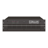
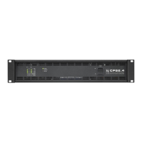
MEASUREMENT SPECIFICATIONS: Force & Eliminator power amplifiers
printed board assembly names and their corresponding EDP-No.:
Force : 84177
Eliminator : 84178
printed board assembly index
Main PCB 1
Supply PCB 4
Input PCB 2
LED PCB 3
measuring condition; if not otherwise specified:
- tolerance of measured values: ∆X = ±1.5 dB
- measuring frequency: f = 1 kHz
- stated levels refer to: U = 775 mV (0 dBu)
- level controls set to their clockwise limits
- pin assignment of the XLR-type connectors: PIN 1: ground / shielding
PIN 2: + INPUT
PIN 3: - INPUT
- source resistance for the induction via the XLR-type connector: R(Q) = 50 Ω
- the AMPLIFIER PCB printed board assembly is provided with service connectors
CNS1 CNS2 CNRC
PIN assignment PIN assignment PIN assignment
1 -Vcc 1 LIM A Switch 1 LIM Out A
2 BIAS +A 2 -15V 2 LIM Out B
3 BIAS -A 3 LIM B Switch 3 Standby via RC
4 FAN Voltage 4 +15V 4 Standby LED
5 +Vcc 5 AGND 5 -Vss
6 BIAS +B 6 Speaker Out A 6 +Vss
7 BIAS -B 7 Relais/Protect 7 n.c.
8 Temp Heatsink 8 Speaker Out B 8 n.c.
1. Operation voltage: U(B) = 120 V, 50 Hz … 60 Hz
2. Deviation limit of the operation voltage: -30 % … +10 %
3. Power consumption (both channels driven) f = 1 kHz
Force Eliminator
idling power consumption 30-60W 40-80W
nominal power consumption (RL=4Ω)
1400W 1900W
standard power consumption (RL=4Ω)
430W 600W
maximum power consumption (RL=4Ω)
1650W 2100W
power consumption at 1/8 of the maximum output power 690W 870W
4. Adjustments
4.1 IDLING CURRENT ADJUSTMENT
Connect the DC-volt meter at the BIAS measuring points (see service connector) and adjust the idling current
via the trim potentiometer VR101/VR301 (on the main PCB printed board assembly). Adjust both channels of
the power amplifier A&B to a value of U(DC) = 7.5 mV. Adjusting the idling current setting has to be