8
DETAILED COMPONENT DESCRIPTIONS
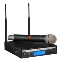
2.1 | Receiver Setup & Operation
1. Placethereceiverandantennaswherethereisaclearlineofsighttotheareawherethe
transmitterwillbeused.Rotatetheantennastoseparatethemby90degrees.
2. Install the appropriate power connection blades into the power supply and con-
nect the power supplycordtothereceiver.PlugthepowersupplyintoanACoutlet.Push
thepowerbuttontoturnthereceiveronandconrmthatitisonbycheckingthemaindisplay
screen.
3. Manual Channel Change
a.The and buttonsallowyoutoscrollthroughtheChannels.WhentheChannel
youdesireisdisplayed,stopscrolling.
b.After2secondsthedisplayedchannelnumberwillstarttoash.
c. Thenumberwillstopashingandthenewchannelisinstalled.
d.TurnonthetransmitterandholdtheEZsyncportfacingthereceiverEZSyncport,
aboutafoot(30cm)away,asdescribedonpage5.
02
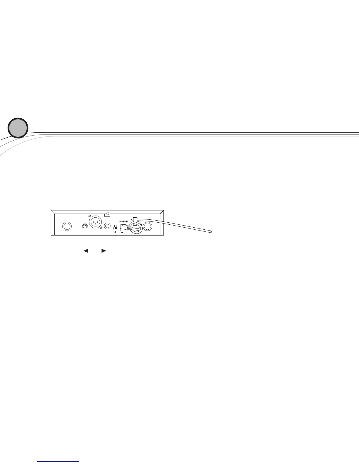
ANTENNA B ANTENNA A12V .500mA
MIN MAX
VOLUME
LEVEL
-10dB 0dB
BALANCED OUT UNBALANCED OUT
continued on next page
 Loading...