2-14 Installation
P/N 0013-1027-005 Rev A
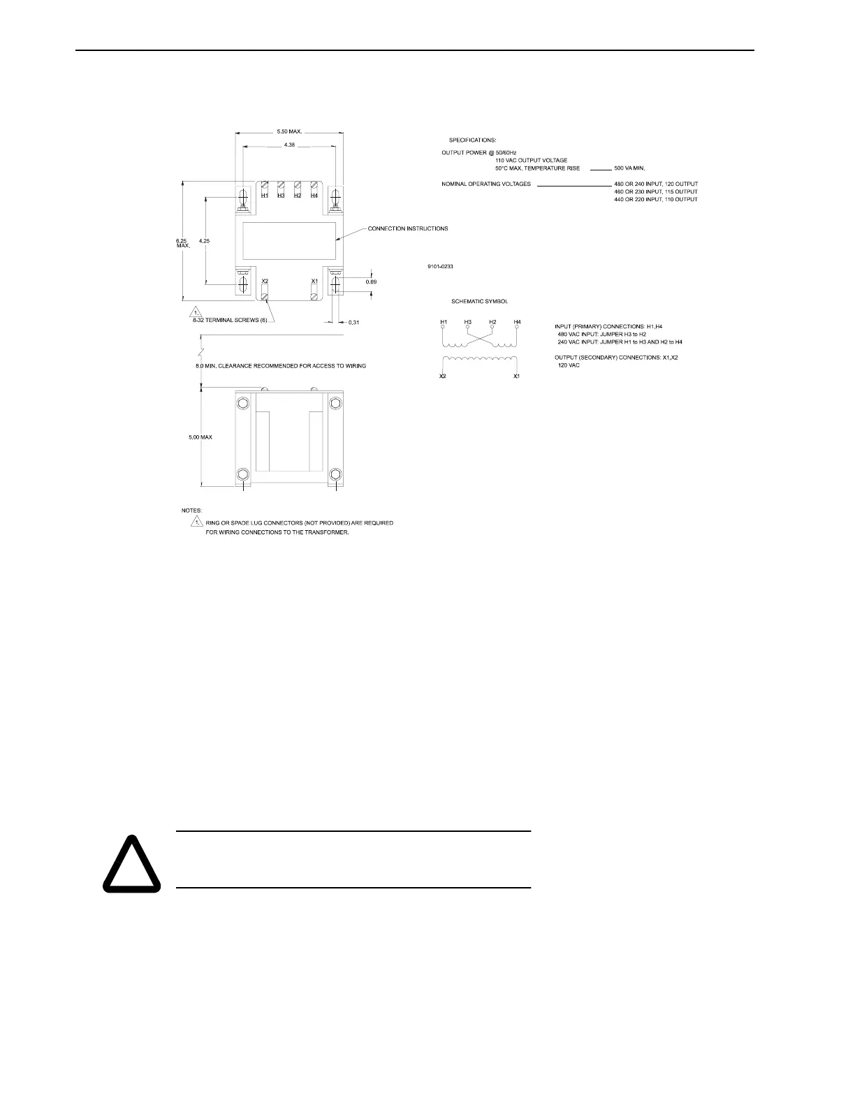
PSM Auxiliary Transformers
Figure 2.10 illustrates mounting dimensions for the PSM Auxiliary Transformer.
Motors
Motor outline drawings which illustrate the mounting dimensions for the F-Series, H-Series,
N-Series, W-Series, and I-Series motors are available in the Electro-Craft catalog and electronic
files in DXF format are available on the BBS for Electro-Craft products.
◆ Do not run motors that are not properly mounted. Attach all motor cables after motor is
mounted.
◆ Mount motor with connectors pointing downward and use a drip loop to keep liquids flow-
ing away from connectors.
◆ Consider motor case temperature if necessary to safeguard operator and maintenance staff.
Maximum case temperature is approximately 100°C (212°F) for a motor used at continuous
rating in a 40°C ambient temperature.
FIGURE 2.10 PSM Auxiliary Transformer Mounting
!
WARNING: Motors can cause extensive damage and injury if
mounted improperly.