3-12 Wiring
P/N 0013-1027-005 Rev A
Analog Input
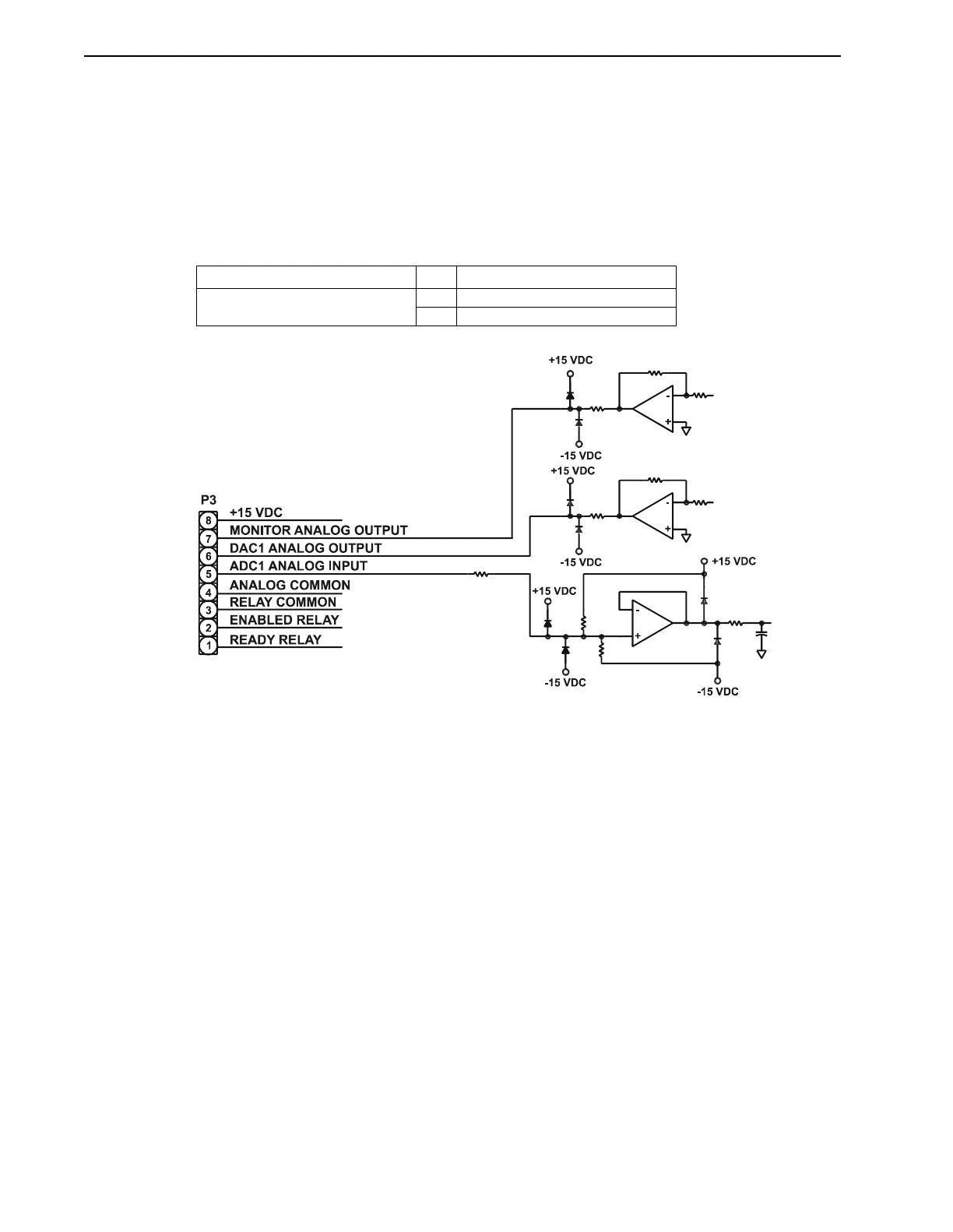
Figure 3.10 illustrates the Analog to Digital converter (ADC) input, ADC1. Located on P3-5, it
may be used to read any analog signal with a range of ±10V. The analog signal ground must be
connected to the Analog Common on connector P3-4. The Analog Common is tied to earth
ground internally. The 10 bit ADC has a resolution of approximately 20 mV. This analog input
may be used as a general purpose analog input or as the feedrate input. Refer to the IQ Master
Instruction Manual for information about the use of this input.
TABLE 3.4 Analog Inputs and Signal Name
Connector Pin Signal Name
P3
Analog I/O and status
4 Analog Common
5 Analog Input (ADC1)
FIGURE 3.10 Analog Input and Output – Typical Internal Circuits