INSTALLATION
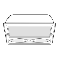
Changing the Front panel
Should you wish to change the front panel mounted on the hood for the accessory panel pro-
vided, proceed as follows:
• Remove the control box guard.
• Remove the three screws fastening the front panel to the sliding
carriage.
• Replace the new front panel, using the screws removed as above.
• Replace the control box guard.
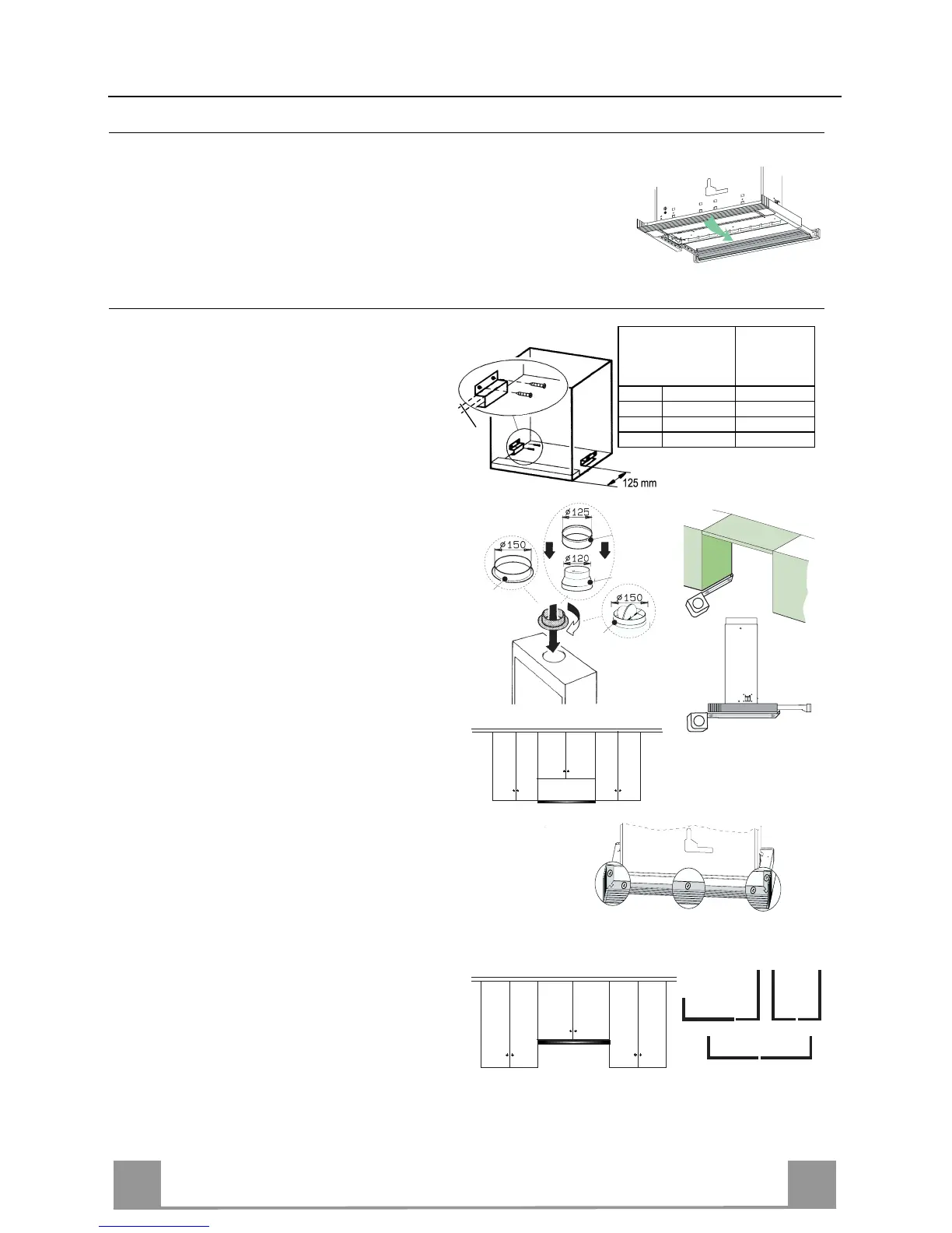
Drilling the Support surface and Fitting the Hood
• The Hood can be installed directly on the un-
derside of wall-mounted units (650 mm min.
from the Cooker Top) using the snap-on side
supports.
• According to requirements, fit two of the
support brackets for the hood (see table fig.
1) at a distance of 125 mm from the front of
the wall-mounted unit.
• According to the chosen air outlet diameter,
insert the appropriate flange into the upper
exhaust outlet. (fig.2)
• Measure the depth of the wall-mounted unit.
(fig.3)
• When the Hood is to be installed not in Line
with the wall-mounted units (fig.4), measure
the depth of the hood plus the plastic fastening
profile 20 (fig. 3).
• Adjust the depth of profile 20 accordingly,
cutting it to size.
• Screw the fastening profile 20 to the rear part
of the hood using the screws 12f (2.9 x 9.5)
provided. (fig.5)
• When installing the Hood in Line with the
wall-mounted units (fig. 6), measure the depth
of the hood.
• Assemble the 2 metal fastening profiles 22
(fig. 7) in such a way that it covers the gap
remaining between the hood and the wall, us-
ing the 3 screws 12f (2.9 x 9.5) provided.
• Screw the resulting profile to the hood body,
using the 3 screws 12f (2.9 x 9.5) provided.