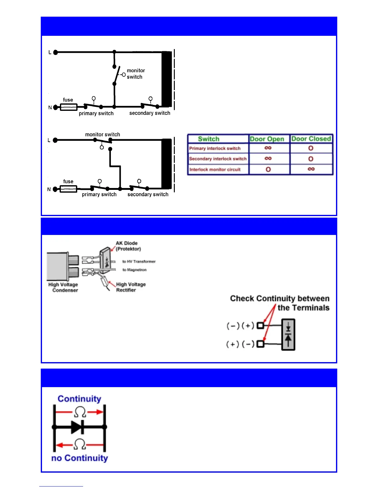
PRIMARY/SECONDARY SWITCH
The measuring of these switches is made with
disconnected connecting leads and when the
door is opened/closed.
MONITORING SWITCH:
It is recommended to measure the passage after
the primary switch. Its connecting lead must be
disconnected.
In any case, the monitoring switch has to short-
circuit the input circuit with an open door.
Required values
In this list you can find the values to be measured
in a table form, in this case >passage< or
>infinite<,.
left: The high-voltage connection diagram of
capacitor and diodes
Attention:
Wrong connections affect an immediate damaging
resp. destruction of components!
Disconnect the mains plug before any measurement!!!
*Short-circuit the capacitor with suitable isolated means
and thus discharge it.
*Check the fuse diode in both directions for passage.
*An intact fuse diode must LOCK in both directions!
- Unplug the oven from the mains!
- Ensure that the capacitor is discharged!
- Disconnect the diode for measurement.
- Measure in both directions using an ohmmeter with the highest
adjustment.
In one direction the diode must lock in full, in another direction you have
to measure a three-digit kOhm value. The measuring instrument must
have a supply voltage of over 9 V, as a certain threshold voltage must
be overcome with this diode.
Measuring the fuse diode (AK-Diode)
Electric checking of the interlock door safety system
Checking the high-voltage diode
created by TSE-N, Reiner Kurzke Page 22