INSTALLATION INSTRUCTIONS | SMART LINE BOILING PAN
22 DOC N° ST0 9183-02 EN | 10-2018
12.3 Frames and fixtures
Foundation or mounting frames and fixtures are
supplied disassembled. These should be as-
sembled according to the following instructions.
NOTE
Please follow these instructions
• Check that the dimensions of the supplied
frames and number marking on the various
fixtures agree with the information in this in-
stallation instruction.
• Check that: Measure R, between the wall and
the mounting frames, is correct to an accur-
acy of +/- 2 mm. (See Fig. 4, 7 and 10)
Frames D/E and fixtures B are screwed together
with the enclosed screws M6S 12x20 (see Fig.
4A-B).
Angle between fixtures and frames is 90° (check
with set square), (see Fig. 3).
R: For measure see subsequent pages
G: Front edge of frame.
Model
foundation frame
PNC
mounting frame
PNC
Left SM6B,
SM6V, SM6P
928031 928034
Left SV6I, SP6I 928032 928035
Right 50-100L 928032 928035
Right 150-300L 928033 928036
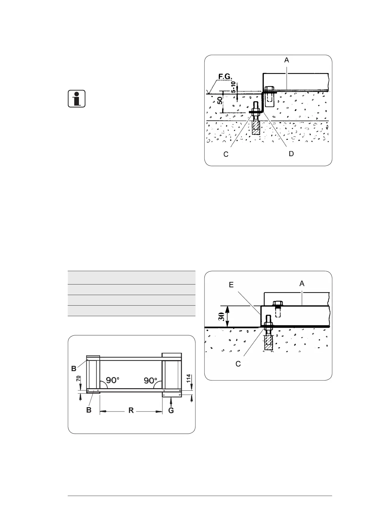
12.3.1 Foundation frames
The foundation frames D are cast:
• So that level A is 5-10 mm above the highest
point of the finished floor
• Horizontal in all directions
• The last part of the frame must be filled with
compound or similar up to Level A
• Expander bolt C, chemical anchor or equival-
ent M10, (not supplied)
• Min. extraction force 500 kp = 4900 N
12.3.2 Mounting frames
The mounting frames E are secured:
• With expander bolt C, chemical anchor or
equivalent M 10, (not supplied)
Min. extraction force 500 kp = 4900 N
• NOTE: The frames are at the same level
• Horizontal in all directions
• The frame must be filled with compound or
similar up to Level A
Fig. 3
Fig. 4A
Fig. 4B