4
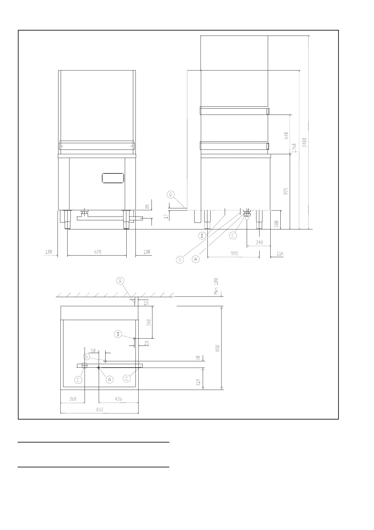
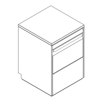
INSTALLATION DIAGRAM WT830EAG / PW1EAG
Fig. 1.a
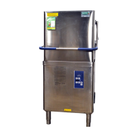
if the appliance is not installed against a wall, suit-
able protection must be provided for the move-
ment of the hood.
Legend Fig. 1.a
B - Water inlet pipe with Ø 3/4” G fittings
C - Threaded waste outlet pipe connector 1” 1/2 G
(Ø 47 mm)
I - Power supply
S - Pipe inlet for detergents
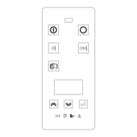
P - Open / close hood
Q - Unipotential screw