8
Install a disconnecting switch with a capacity at
least equal to that given in the technical data table,
a 30mA residual current circuit breaker and an
overcurrent device (magnetothermal cut-out with
manual reset or fuse) between the appliance and
the mains power outlet.
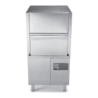
RATING PLATE
The rating plate contains identification and technical
data and is located on the right-hand side panel of the
appliance (Fig. 5).
Fig. 5
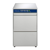
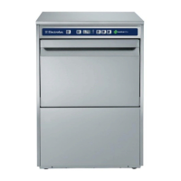
B1 WATER CONNECTION
• Position the dishwasher and level the appliance by
turning the relative height-adjustable feet (Fig. 5).
• Connect the appliance water supply pipe “A”
(Fig. 1.a/Fig. 1.b) to the mains, fitting a cut-off cock,
the filter provided and a pressure gauge between
the appliance and the mains (Fig. 6).
Fig. 6
• Check that the dynamic water supply pressure,
measured between the appliance and the main, is
between 50 and 700 kPa for machines with atmos-
pheric boiler (test while dishwasher tank or boiler is
filling with water).
If the pressure is too high, fit a suitable pres-
sure reducer on the inlet pipe.
Connect the waste outlet pipe “C” (Fig. 1.a/Fig. 1.b) to
the main drain pipe, fitting a trap, or place the outlet
pipe over an S trap set into the floor.
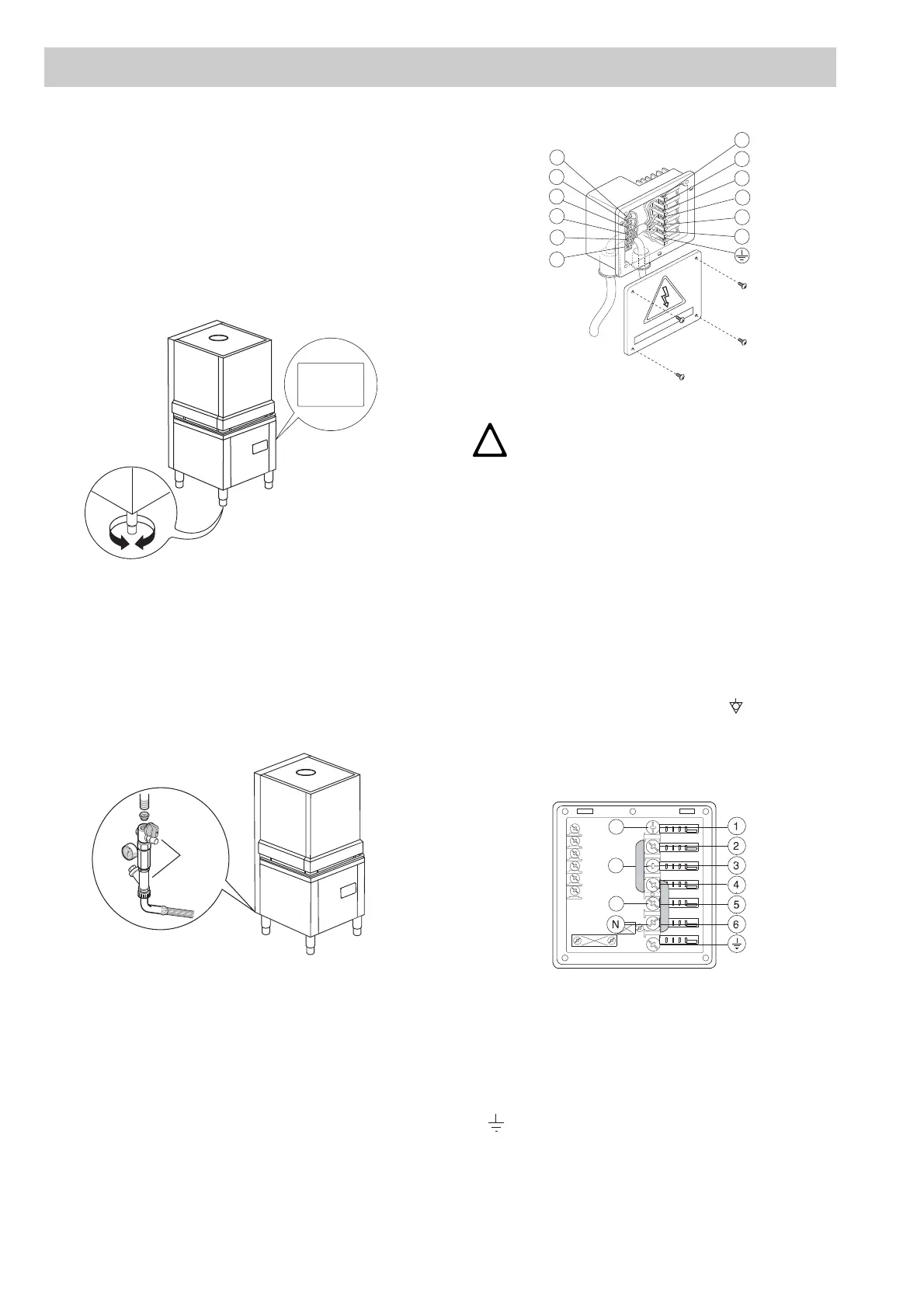
B2 ELECTRICAL CONNECTION
Fig. 7
• Before carrying out the electrical connection, check
that the voltage and frequency on the appliance rat-
ing plate correspond to those of the mains electric-
ity supply.
• The earth wire at the terminal end must be longer
(max. 20 mm) than the phase wires.
• Connect the earth wire of the power supply cable to
an efficient earth clamp. The appliance must also
be included in a unipotential system, the connec-
tion being made through the screw “Q” (Fig. 1.a/
Fig. 1.b) marked with the symbol “ ”. The unipo-
tential wire must have a cross section of 10 mm
2
.
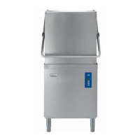
Power supply 400…415V 3N
(standard configuration)
Fig. 8
Open the power supply terminal board and insert the
jumpers provided as follows: one jumper between termi-
nals 2 and 4 and another between terminals 4 and 6.
Using a suitable power supply cable (see technical data
table), connect the three phases to terminals 1, 3 and 5,
the neutral to terminal 6 and the earth wire to the termi-
nal .
B INSTRUCTIONS FOR THE INSTALLER/MAINTENANCE PERSON
Model WT830 EA
PNC 9CGX 531300 05 Ser.N .123000001
AC 400V 3N 50Hz
Power Boiler 16500w
Power Tank 7500w
Power Max 26800w
Made in EEC
Model WT830 EA
PNC 9CGX531300 05
Ser.N .123000001
CAUTION
THE EARTH AND ELECTRICAL CON-
NECTIONS SHOULD BE IN COMPLI-
ANCE WITH NATIONAL REGULATIONS.
A
C 400....
1
11
10
9
8
7
6
5
4
3
2
12